
Operation device for engine

a technology for operating devices and engines, which is applied in the direction of combustion engines, combustion air/fuel air treatment, charge feed systems, etc., can solve the problems of increasing the number of revolutions of the engine and cost of products, so as to avoid such an undesired increase in the number of revolutions, increasing the size, weight and cost of products

Inactive Publication Date: 2014-10-14
SUBARU CORP
View PDF8 Cites 7 Cited by
  • Summary
  • Abstract
  • Description
  • Claims
  • Application Information

AI Technical Summary

Benefits of technology

The present invention provides an operation device for an engine that allows for a simple and flexible relationship between the operation of an operation unit and the throttle opening. This is achieved through a link member, cam member, and cam follower mechanism that can be easily adjusted to prevent an increase in engine revolutions due to increased fuel consumption during a choking operation. The invention also allows for easy adjustment of the throttle opening to achieve desired engine revolutions and provides a mechanism for controlling the maximum number of revolutions. Overall, the invention provides a simple and flexible solution for controlling engine performance.

Problems solved by technology

However, in the above-described conventional art, even though the maximum number of revolutions is controlled by the stopper, the number of revolutions of the engine is further increased due to an increase in fuel consumption when the choke is in operation.
However, in this case, the structure becomes complicated, the number of the parts increases, and the size, weight, and cost of product also increase.

Method used


Image

  • Operation device for engine
  • Operation device for engine
  • Operation device for engine

Examples


embodiment

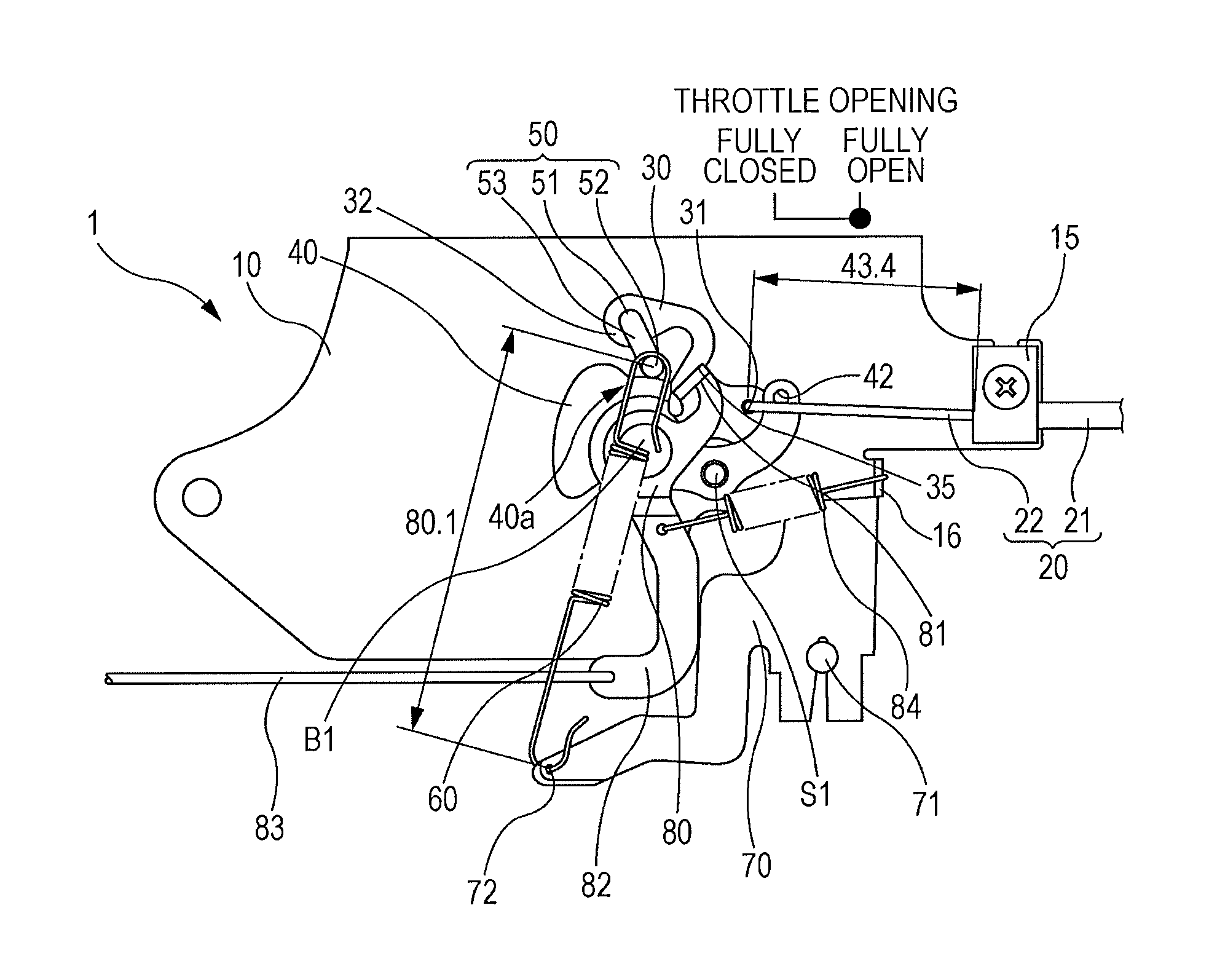
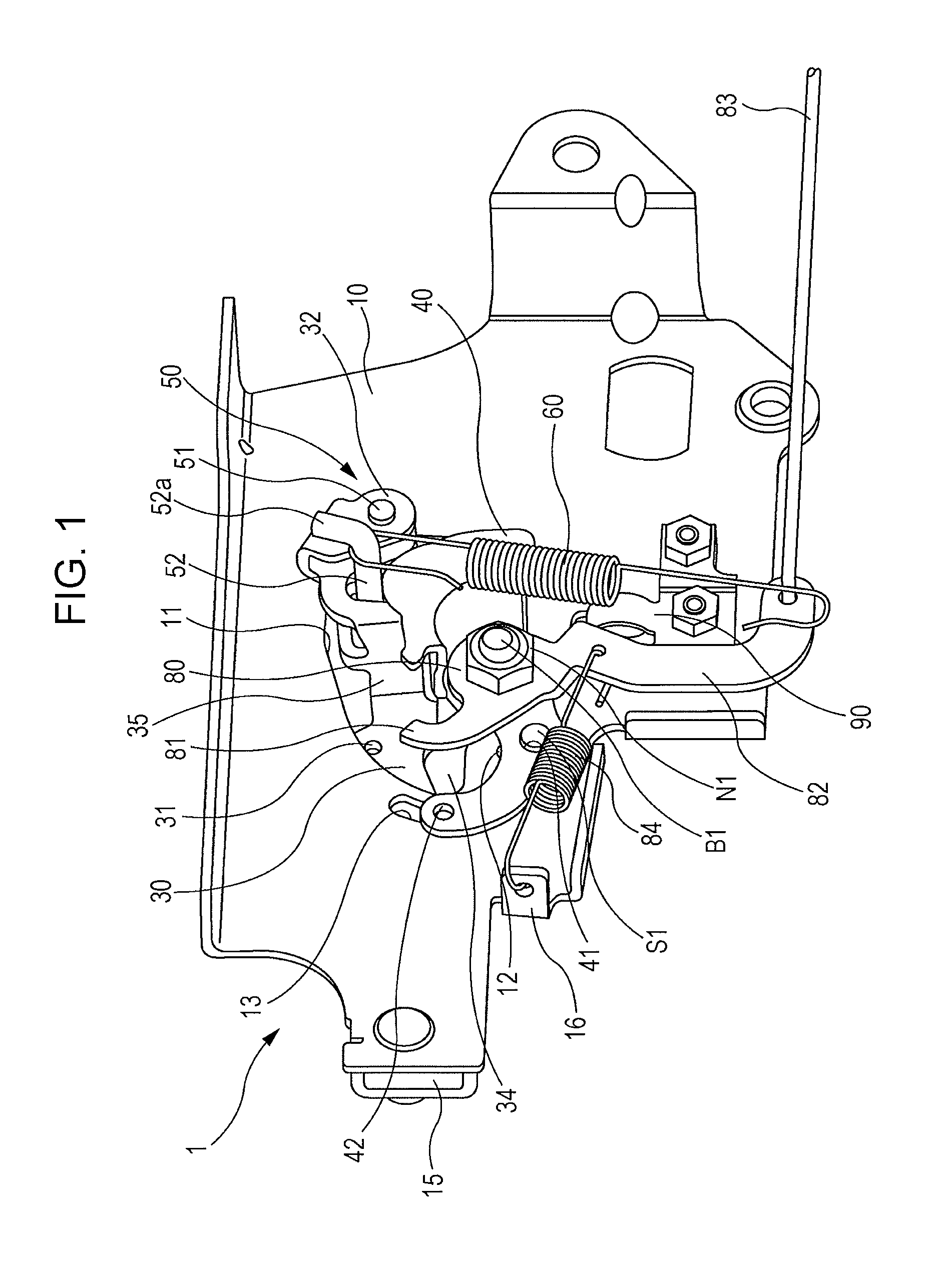
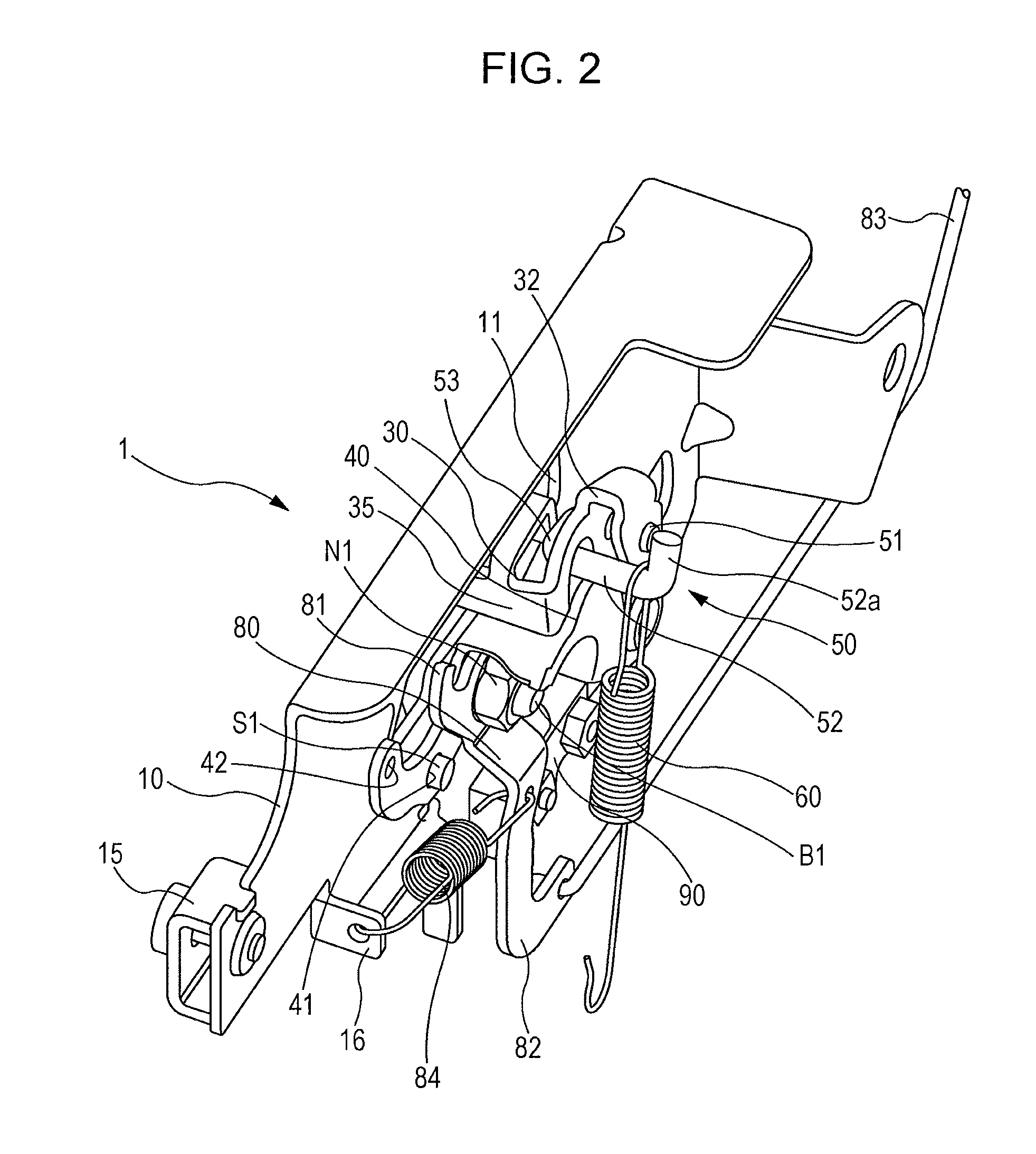
[0021]Hereinafter, an embodiment of an operation device to which the present invention is applied will be described. The operation device of the embodiment is installed, for example, in a mowing machine which uses what is called a V-shaft general-purpose engine as a power source, in which a crankshaft is arranged in the vertical direction. The type of an engine to which the operation device is applied, and the type of a machine to be driven by the engine are not necessarily the above types, and are not specifically limited. The operation device adopts a configuration which allows an operator to open and close a throttle, turn on and off a choke, and stop the engine by operating a single lever which is disposed apart from the engine. FIGS. 1 to 4 are external perspective views of the operation device of the embodiment. FIGS. 5 to 9 are diagrams illustrating the positional relationships between the members in the operation device of the embodiment in respective states of a choke-on st...


PUM


Abstract

There is the operation device for an engine. An operation device for an engine performs a throttle operation of the engine which is disposed apart from an operation unit operated by an operator. The operation device includes: a link member rotatable with respect to a base in response to an operation of the operation unit; a cam member fixed to the base, and disposed at a distance from the center of rotation of the link member, the distance changing continuously according to the angular position of the cam member around the center of rotation; a cam follower connected to the link member and configured to along the cam member; and a throttle drive member for connecting the cam follower to a throttle operation unit of the engine.

Description

CROSS-REFERENCE TO RELATED APPLICATIONS[0001]The present application claims priority from Japanese Patent Application No. 2011-204359 filed on Sep. 20, 2011, the entire contents of which are hereby incorporated by reference.BACKGROUND OF THE INVENTION[0002]1. Field of the Invention[0003]The present invention relates to an operation device for an engine which performs a throttle operation of an engine where the operation device is disposed apart from an operation unit, and particularly relates to an operation device which increases the degree of freedom in setting the relationship between an operation amount of the operation unit and a throttle opening with a simple structure.[0004]2. Description of the Related Art[0005]For example, in an engine-driven mowing machine or the like, an operation unit such as a lever to be operated by an operator during a machine operation may be disposed apart from the engine body. In such a case, it is demanded that an operation device have a configura...

Claims


Application Information

Patent Timeline
Patent Type & Authority Patents(United States)
IPC IPC(8): F02B33/00F02D11/04F02D9/10
CPCF02D9/1065F02D11/04
Inventor FURUYA, AKIRA
Owner SUBARU CORP
Learn More