Display device

a technology of display device and display screen, which is applied in the direction of lighting and heating apparatus, instruments, machines/engines, etc., can solve problems such as quality degradation of display screen, and achieve the effect of preventing quality degradation

Active Publication Date: 2014-10-21
JAPAN DISPLAY INC
View PDF7 Cites 19 Cited by
  • Summary
  • Abstract
  • Description
  • Claims
  • Application Information

AI Technical Summary

Benefits of technology

[0007]The present invention has an object to provide a display device which is capable of blocking leakage light from a light guide plate to prevent quality degradation.
[0008](1) According to an exemplary embodiment of the present invention, there is provided a display device, including: a display panel; and a backlight unit to be used as a planar light source of the display panel. The backlight unit includes: a light source having an emission region narrower than an emission region of the planar light source; a wiring board having the light source mounted thereon; a light guide plate having an end surface into which light from the light source enters, and a front surface from which the light exits; a light-shielding pressure-sensitive adhesive sheet for causing the wiring board to adhere to an end portion of the front surface of the light guide plate; and a light diffusion sheet which overlaps with the front surface of the light guide plate. The front surface of the light guide plate includes an effective region serving as the planar light source and a light entering region ranging from the end surface into which the light enters to the effective region. The wiring board and the light-shielding pressure-sensitive adhesive sheet each have a part positioned in the light entering region. The light diffusion sheet is arranged from the effective region to the light entering region, and at least an end portion thereof overlaps with the light-shielding pressure-sensitive adhesive sheet in the light entering region. On a side closer to the effective region with respect to the light-shielding pressure-sensitive adhesive sheet, the light entering region is covered with the light diffusion sheet without a gap. According to the exemplary embodiment of the present invention, the light diffusion sheet and the light-shielding pressure-sensitive adhesive sheet are provided in an overlapping manner without a gap. Therefore, the leakage light from the light guide plate can be blocked to prevent quality degradation.

Problems solved by technology

Therefore, when the display panel is obliquely viewed, the light of the LED may be directly observed, which causes a problem of display quality degradation.

Method used


Image

  • Display device
  • Display device
  • Display device

Examples


Embodiment Construction

[0022]Hereinafter, an embodiment of the present invention is described with reference to the drawings.

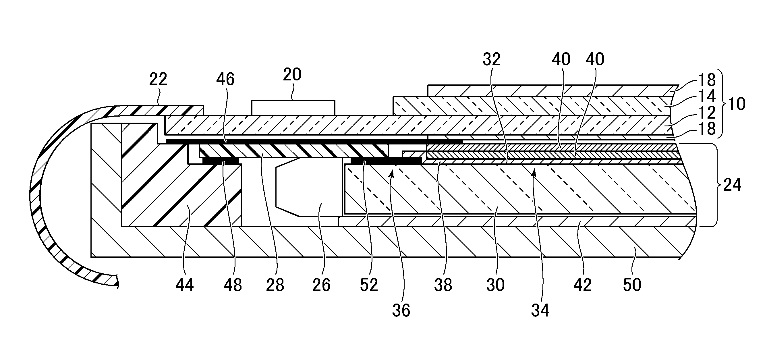
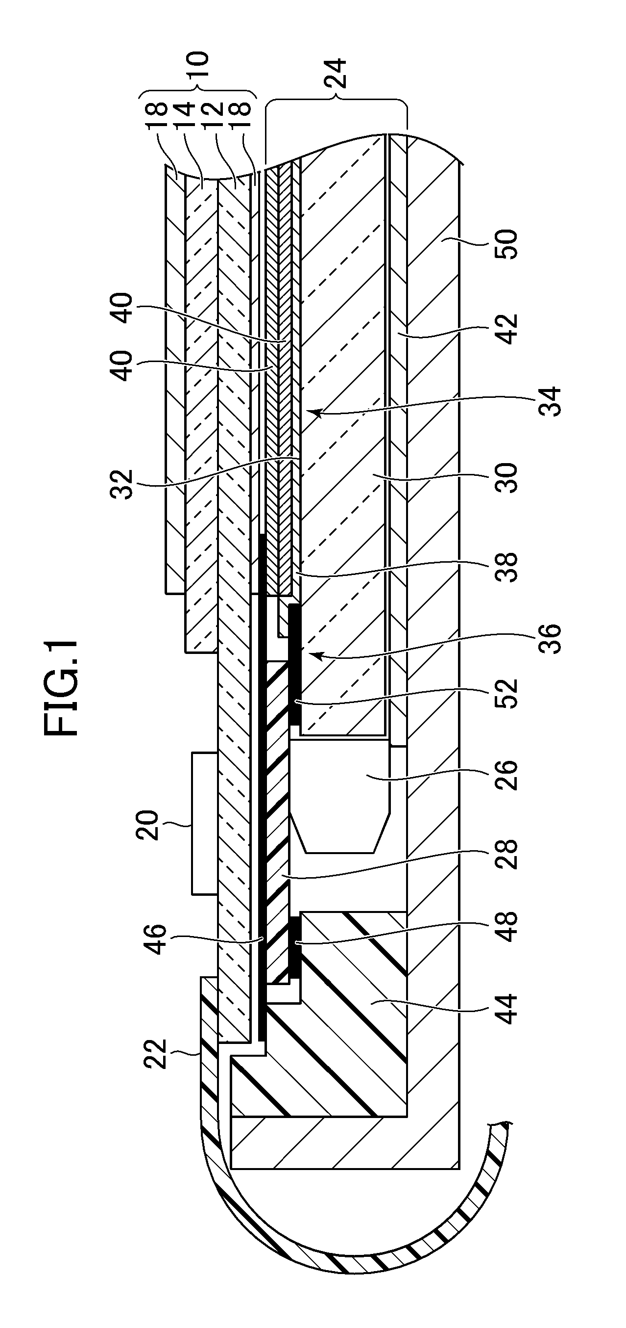
[0023]FIG. 1 is a sectional view illustrating a display device according to an embodiment to which the present invention is applied. The display device includes a display panel 10. The display panel 10 is a light-shutter type display panel which controls passing and blocking of light to display an image. The display panel 10 illustrated in FIG. 1 is a liquid crystal display panel, and includes a pair of substrates 12 and 14 made of glass and the like, liquid crystal (not shown) sandwiched between the substrates, and polarizing plates 18 arranged on outer sides of the pair of substrates 12 and 14, respectively.

[0024]One substrate (lower substrate in FIG. 1) 12 extends off from another substrate (upper substrate in FIG. 1) 14. On a surface of the one substrate 12 on a side opposed to the another substrate 14 in a part which extends off from the another substrate 14, there is mounted a...


PUM

PropertyMeasurementUnit
pressure-aaaaaaaaaa
pressureaaaaaaaaaa
light-shielding pressure-sensitiveaaaaaaaaaa

Abstract

A backlight unit includes: a wiring board having a light source mounted thereon; a light guide plate; a light-shielding pressure-sensitive adhesive sheet; and a light diffusion sheet. The front surface of the light guide plate includes an effective region serving as the planar light source and a light entering region ranging from the end surface into which the light enters to the effective region. The wiring board and the light-shielding pressure-sensitive adhesive sheet each have a part positioned in the light entering region. The light diffusion sheet is arranged from the effective region to the light entering region, and overlaps with the light-shielding pressure-sensitive adhesive sheet in the light entering region. On a side closer to the effective region with respect to the light-shielding pressure-sensitive adhesive sheet, the light entering region is covered with the light diffusion sheet without a gap.

Description

CROSS-REFERENCE TO RELATED APPLICATION[0001]The present application claims priority from Japanese application JP 2011-177436 filed on Aug. 15, 2011, the contents of which are hereby incorporated by reference into this application.BACKGROUND OF THE INVENTION[0002]1. Field of the Invention[0003]The present invention relates to a display device.[0004]2. Description of the Related Art[0005]In a display device including a side-light type backlight unit, light entering an end surface of a light guide plate travels inside the light guide plate and exits from a front surface of the light guide plate (Japanese Patent Application Laid-open No. 2009-276531). As a light source of the backlight unit, a light emitting diode (LED) is generally used. The LED is mounted on a flexible wiring board and is arranged so as to face the end surface of the light guide plate. Further, an optical sheet is arranged on the front surface of the light guide plate.[0006]When the flexible wiring board is fixed to a...

Claims


Application Information

Patent Timeline
Patent Type & Authority Patents(United States)
IPC IPC(8): G02F1/1335F21V8/00F21V7/22
CPCG02B6/0053G02B6/0013G02B6/0083G02F2001/133612G02B6/0055G02F1/133615G02B6/0088G02F1/133612G02B6/0023G02B6/0051
Inventor MOTOOKA, MUNENORISUZUKI, NOBUYUKI
Owner JAPAN DISPLAY INC
Why Eureka
Try Eureka