
Polymer composition having photoalignable group, liquid crystal alignment film formed of the polymer composition, and liquid crystal display device having phase difference plate formed of the liquid crystal alignment film

a polymer composition and photoaligning technology, which is applied in the field of photoalignable polymer compositions, liquid crystal alignment films formed of polymer compositions, optical films having liquid crystal alignment films, etc., can solve the problems of dust or static electricity generation, luminance and contrast may occasionally decrease, and achieve high optical uniformity, excellent sensitivity to allow photoalignment, and high alignment stability

Inactive Publication Date: 2014-10-21
JNC CORP +1
View PDF7 Cites 1 Cited by
  • Summary
  • Abstract
  • Description
  • Claims
  • Application Information

AI Technical Summary

Benefits of technology

[0053]A photoalignable polymer composition of the invention contains a specific photoalignable polymer and a specific non-photoalignable polymer. Therefore, a photoalignable film obtained by applying a photoaligning agent including the composition to a base material or the like and drying an applied surface thereon has an excellent sensitivity to allow photoalignment even with exposure in a short period of time. Furthermore, a liquid crystal alignment film is formed by a photoalignment method. Therefore, a complicated treatment process is not required, and neither dust nor static electricity is subsequently generated, while the complicated process and generation of dust and static electricity are seen in a rubbing treatment that has been applied so far. Therefore, a liquid crystal alignment film having a high optical uniformity without an alignment defect can be prepared. Thus, a phase difference plate manufactured using the liquid crystal alignment film can keep a high alignment stability.

Problems solved by technology

However, a viewing angle at which an image can be properly visually recognized is narrow in the liquid crystal display devices, and when the image is viewed from an oblique direction, luminance and contrast may be occasionally decreased, and luminance inversion may be occasionally caused in a halftone.
However, dust or static electricity is generated or the like by the rubbing method.
Thus, an alignment defect or an influence of dust or static electricity on the liquid crystal device is regarded as a problem.
Moreover, in the case of a patterned phase difference film, control of an alignment pattern by the rubbing treatment is difficult.
Therefore, when polyimide is obtained by applying a solution containing polyamic acid and a high boiling point solvent onto the substrate of the plastic and heating the substrate at a high temperature, use of the resultant polyimide as the liquid crystal alignment film has been difficult in some cases.
Furthermore, TAC has a low solvent resistance.
Therefore, a solvent that can be used is limited according to the method by which the film is prepared by applying an aligning agent to be the liquid crystal alignment film onto the substrate.
For example, polyamic acid that has been used for forming polyimide so far has a low solubility in the solvent that can be applied to TAC, which has been a problem.

Method used


Image

  • Polymer composition having photoalignable group, liquid crystal alignment film formed of the polymer composition, and liquid crystal display device having phase difference plate formed of the liquid crystal alignment film
  • Polymer composition having photoalignable group, liquid crystal alignment film formed of the polymer composition, and liquid crystal display device having phase difference plate formed of the liquid crystal alignment film
  • Polymer composition having photoalignable group, liquid crystal alignment film formed of the polymer composition, and liquid crystal display device having phase difference plate formed of the liquid crystal alignment film

Examples


synthesis example 1

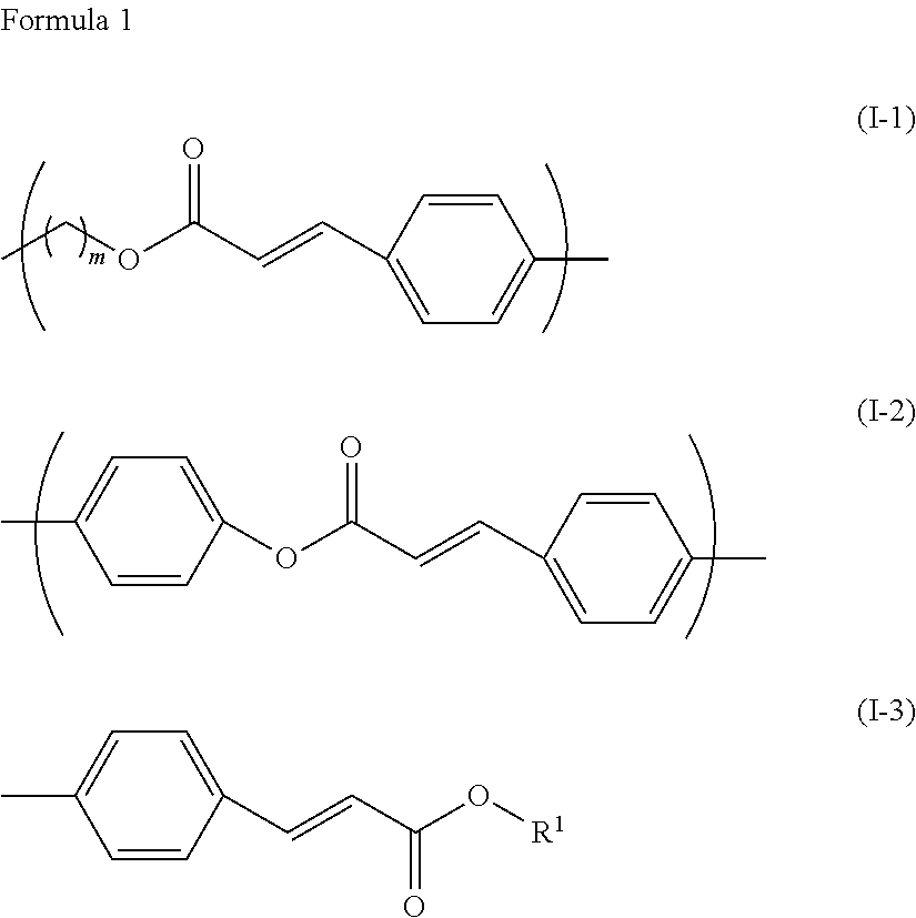
[0161]Monomer (1-1) having a photoalignable group (as included in monomer I-1-1-a described above) was prepared as described below.

[0162]

[0163]Then, 22.8 g of methoxycinnamic acid, 16.7 g of 2-hydroxybutyl methacrylate and 3.2 g of 4-dimethylaminopyridine (DMAP) were added to 230 mL of dichloromethane, and the resultant mixture was agitated under a nitrogen atmosphere. Thereto, 60 mL of dichloromethane solution containing 27.7 g of 1,3-dicyclohexylcarbodiimide (DCC) was added dropwise. After dropwise addition, the resultant mixture was agitated at room temperature for 8 hours. A precipitate formed was filtered off, and an organic layer was washed with water and dried over anhydrous magnesium sulfate. A solvent was distilled off under reduced pressure, a residue was purified by means of column chromatography, and recrystallized in ethanol, and thus 30.0 g of monomer (1-1) having the photoalignable group was obtained. Measurement results of phase transition temperature and nuclear mag...

synthesis example 2

[0166]Monomer (1-2) having a photoalignable group (as included in monomer I-2-1-a described above) was prepared as described below.

[0167]

(First Step)

[0168]Then, 1,120 mmol of ethyl 4-hydroxycinnamate, 1,230 mmol of sodium hydroxide and 120 mmol of sodium iodide were added to 1,000 mL of N,N-dimethylformamide (DMF), and the resultant mixture was agitated at 60° C. under a nitrogen atmosphere. Thereto, 1,230 mmol of 6-chlorohexanol was added dropwise. After dropwise addition, the resultant mixture was agitated at 80° C. for 8 hours. Ethyl acetate and water were added to a reaction mixture, and an organic layer was extracted. The resultant organic layer was washed with water and dried over anhydrous magnesium sulfate. A solvent was distilled off under reduced pressure. The resultant residue and 1,230 mmol of sodium hydroxide were added to a mixed solution of 800 mL of water and 800 mL of methanol, and the resultant mixture was agitated for 3 hours under heating reflux. A solvent was di...

synthesis example 3

[0173]Monomer (1-3) having a photoalignable group (as included in monomer I-3-1-a described above) was prepared as described below.

[0174]

(First Step)

[0175]Then, 50 g of 2-hydroxybutyl methacrylate and 50 mL of pyridine were added to 150 mL of toluene, 80 g of p-toluenesulfonic acid chloride was added under cooling, and the resultant mixture was agitated at room temperature for 16 hours under a nitrogen atmosphere. A precipitated salt was removed by filtration under reduce pressure. Water (100 mL) was added to a filtrate, and the resultant mixture was agitated at 40° C. for 2 hours. An organic layer was separated, and the resultant organic layer was sequentially washed with 2 N hydrochloric acid, a saturated aqueous solution of sodium hydrogencarbonate, and water, and dried over anhydrous magnesium sulfate. Toluene was distilled off under reduced pressure, and thus 98 g of crude colorless liquid (ex-3) was obtained.

(Final Step)

[0176]Then, 30 g of compound (ex-4) and 7.4 g of sodium h...


PUM

PropertyMeasurementUnit
mass ratioaaaaaaaaaa
boiling pointaaaaaaaaaa
temperatureaaaaaaaaaa

Abstract

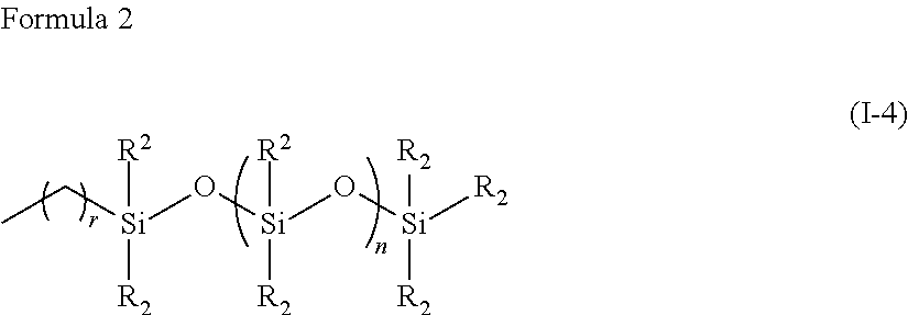
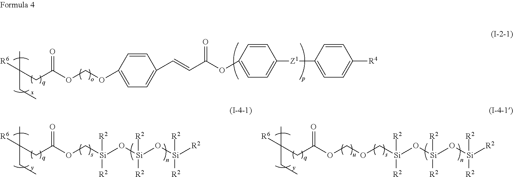
To provide a photoalignable material that can yield a photoalignable film having a high optical uniformity and no alignment defect, and allows photoalignment with exposure in a short period of time. A photoalignable polymer composition containing a specific photoalignable polymer having a silicone group or a fluorine-substituted alkyl group, and a photoalignable group, and a specific non-photoalignable polymer is manufactured, and the photoalignable film is manufactured by applying the polymer composition onto a base material or the like, drying an applied surface thereon, and irradiating the applied surface with light.

Description

TECHNICAL FIELD[0001]The present invention relates to a photoalignable polymer composition, a liquid crystal alignment film formed of the polymer composition, an optical film having the liquid crystal alignment film, and an optical device such as a liquid crystal display device having the optical film. More specifically, the invention relates to a photoalignable polymer composition having a low refractive index, and an excellent transparency, liquid crystal alignment ability, solvent resistance and heat resistance, and an application using the same to an optical use. The photoalignable polymer composition of the invention is suitable particularly for a patterned phase difference plate used for a passive glasses 3D display, a built-in phase difference plate in a liquid crystal display, a color filter overcoat having an optical alignment function, or the like.BACKGROUND ART[0002]A liquid crystal display device is used in various kinds of liquid crystal display devices, including a mon...

Claims


Application Information

Patent Timeline
Patent Type & Authority Patents(United States)
IPC IPC(8): C08L83/06C08L33/16C08L83/10C08F30/08G02F1/1337C08L33/14
CPCC08L33/14C08L33/16G02F1/1337C08L83/10C08F30/08C08L83/06Y10T428/1005C08L33/12Y10T428/1014G02F1/133711C09K19/56C09K2323/02C09K2323/023C08L33/04C08L101/02G02B5/30G02F1/1335
Inventor TANABE, MAYUMIOOTSUKI, DAISUKEKUBOUCHI, KIE
Owner JNC CORP
Learn More