
Enhanced mobile satellite communication system

a mobile satellite and communication system technology, applied in the direction of antenna adaptation in movable bodies, radio transmission, transmission, etc., can solve the problems of inability to meet the needs of mobile satellite antenna systems, equipment being lost or misplaced, and being too large for the purpose of missions, so as to lessen the chances of incompatible power input situations, and improve the versatility of mobile satellite antenna system product range.

Inactive Publication Date: 2014-10-21
PATHFINDER DIGITAL
View PDF32 Cites 7 Cited by
  • Summary
  • Abstract
  • Description
  • Claims
  • Application Information

AI Technical Summary

Benefits of technology

This patent is about a mobile satellite communication system that improves versatility and reduces power input incompatibility. It is easy to assemble, disassemble, and transport. The system also includes test sample ports for monitoring and troubleshooting. The patent describes a mobile satellite communication terminal system which includes an antenna dish, feed boom assembly, power supply unit, and grip case. The power supply unit is received in the grip case. A transport container is provided for efficient and convenient storage, transport, assembly, and disassembly of the system.

Problems solved by technology

These systems are generally used for a variety of different types of communications scenarios, meaning that in some cases excess equipment is transported in the missions.
The transfer or transport of a number of cases raises the likelihood of equipment getting lost or misplaced and these systems tend to be less robust in the sense that damaged or broken parts occur that tend to degrade performance.
In addition, assembly and disassembly of the system in the field can be time consuming when, often, time is of the essence.

Method used


Image

  • Enhanced mobile satellite communication system
  • Enhanced mobile satellite communication system
  • Enhanced mobile satellite communication system

Examples


Embodiment Construction

Schematic Overview of the SatCom Terminal

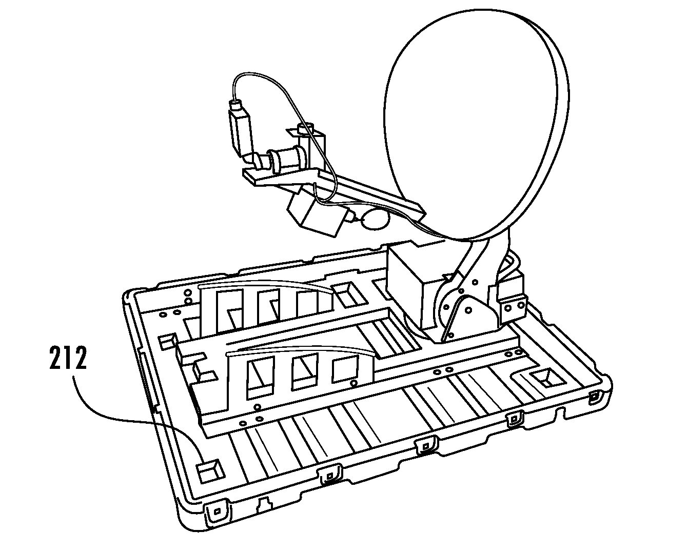
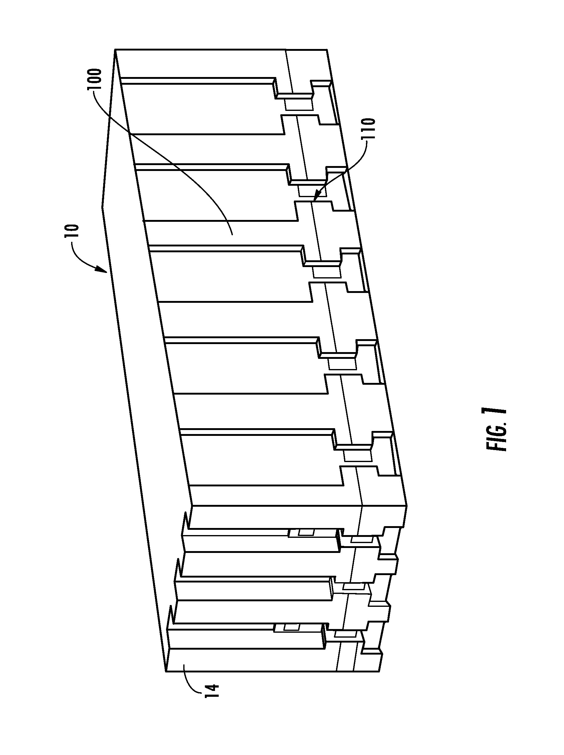
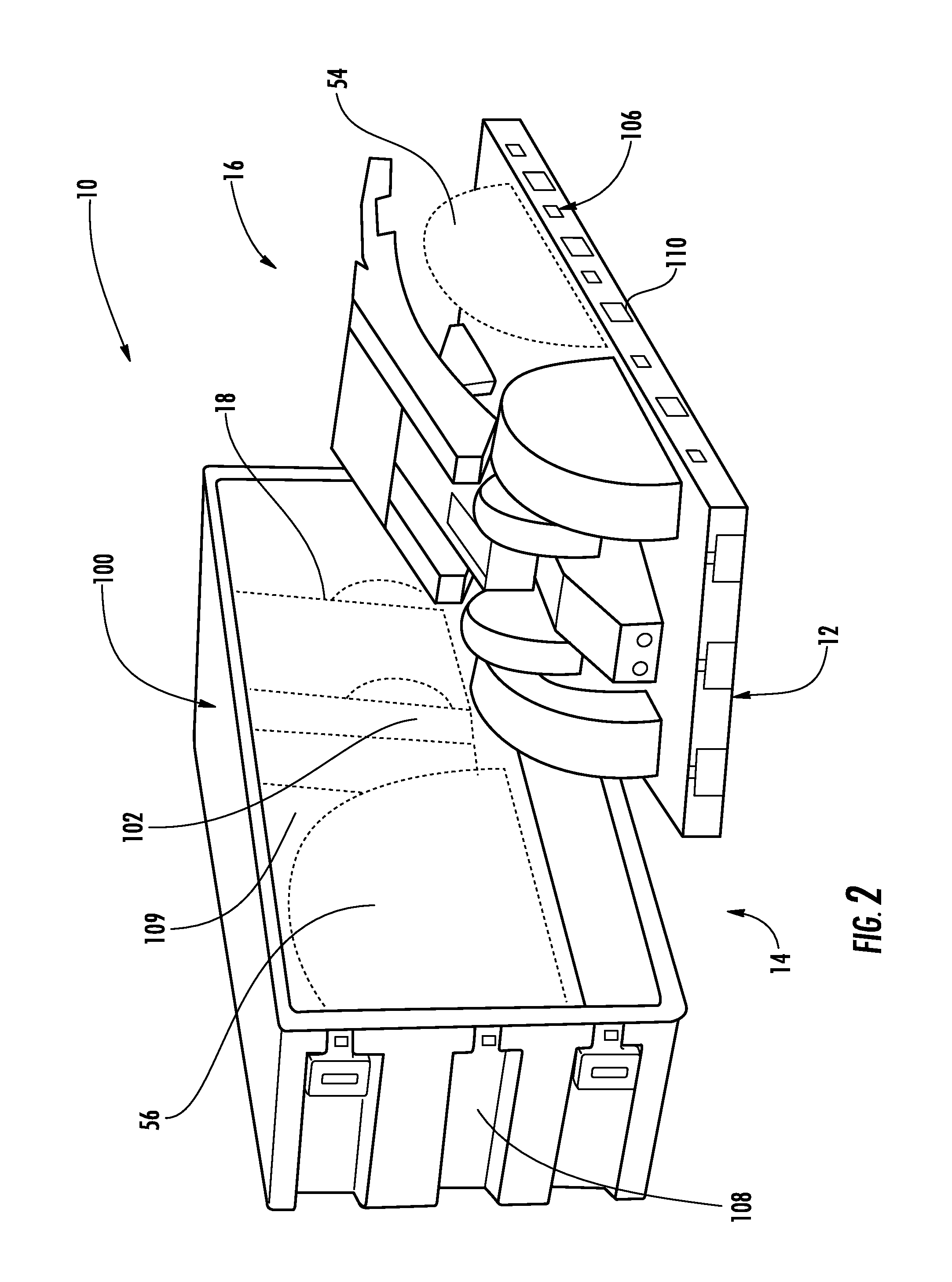
[0037]With reference now to FIGS. 1-17, one embodiment of the mobile satellite communication system of the present invention will be described and is generally designated, as seen in FIG. 1, as a SatCom terminal 10. As seen in FIG. 2, the SatCom terminal 10 includes a transmit / receive sub-system 12 and a transport container 14. The transport container includes tray 106 and cover 108. The transmit / receive sub-system 12 comprises an antenna dish and feed boom assembly, hereinafter sometimes designated as the tray mounted unit 16, and a grip case 18 having a power supply unit (PSU) 13 and an antenna controller assembly 46, shown in FIG. 10, received in the grip case. The transport container 14 is specially configured to stow and carry the grip case 18 in a secure mounting and to stow and carry the tray mounted unit 16 in a secure mounting.

[0038]The SatCom terminal 10 is advantageously suited for use for transmitting and receiving signals from a ...


PUM


Abstract

There is provided a mobile satellite communication terminal system including a transmit / receive sub-system. The transmit / receive sub-system includes an antenna dish, a feed boom assembly, and a power supply unit having a first power input adapted to receive alternating current power and a second power input adapted to receive direct current power. The power supply unit is able to operate on either alternating current or direct current for supplying power to the transmit / receive sub-system. The power supply unit is received in a grip case. A transport container is provided. The antenna dish, the feed boom assembly, and the grip case are received in the transport container.

Description

RELATED APPLICATION[0001]This is a U.S. non-provisional application relating to and claiming the benefit of U.S. Provisional Patent Application Ser. No. 61 / 406,651 filed Oct. 26, 2010.BACKGROUND OF THE INVENTION[0002]A mobile satellite antenna is particularly suited for high bandwidth communication between a remote location and a satellite. For example, commercial users such as those found in the oil and gas industry can advantageously deploy a mobile satellite antenna where use locations are far apart. Additionally, some users of mobile satellite antennas require high speed deployment of the satellite antenna such as, for example, users in the law enforcement community with tactical communications vehicles. Military and homeland security units also desire a mobile satellite antenna that is configured as a high bandwidth uplink / downlink mobile satellite antenna system that can be quickly disassembled, stowed, and transported to another location.[0003]There have been a number of sate...

Claims


Application Information

Patent Timeline
Patent Type & Authority Patents(United States)
IPC IPC(8): H04B7/185H01Q1/32
CPCH04B7/18517H01Q19/13H01Q1/1235H01Q1/32H04B7/185
Inventor TARPLEY, JR., RICHARD, A.
Owner PATHFINDER DIGITAL
Learn More