Waste processing

a technology of waste processing and waste, applied in the field of waste processing, can solve the problems of not being able to reuse, not being able to achieve manual separation, and pyrolysis of plastic,

Active Publication Date: 2014-10-28
CHINOOK END STAGE RECYCLING
View PDF16 Cites 4 Cited by
  • Summary
  • Abstract
  • Description
  • Claims
  • Application Information

AI Technical Summary

Benefits of technology

[0009]In this manner, as the plastic starts to melt and becomes flowable it is physically separated from the metal thereby allowing both the metal and the plastic components to be recovered for re-use without the need for labor intensive processes.
[0015]In a preferred embodiment the method comprises passing hot air into a chamber containing the rotating drum so that it passes over the material therein and exits via an elongate slot extending along the length of the chamber so as to remove any dust or dirt form the exterior of the cables. The hot gas may have water injected into is so that the water assists in cleaning the exterior of the material in the chamber. Once the plastic has substantially been cleaned a valve downstream of the elongate slot is closed so as to prevent further gas flow therethrough and a valve downstream of a main chamber outlet, situated substantially coaxially with the chamber in the bottom thereof is opened.
[0024]In this manner, as the plastic starts to melt and becomes flowable it is physically separated from the metal thereby allowing both the metal and the plastic components to be recovered for re-use without the need for labor intensive processes.

Problems solved by technology

However, when the metals are coated in other substances this can prove to be difficult and specialized processes are used for removing the coatings.
While this method is effective for recovering the metal and energy is recovered from the non metal components there are several problems associated with this technology when trying to recycle material substantially comprising a low melting point plastic and metal.
Secondly the plastic is pyrolysed and is not recovered from the process.
Accordingly, although energy is recovered from the plastic component of the waste it cannot be reused.
While this method is effective it is not financially viable for manual separation in many countries as the cost of labor is too high in comparison to the value of the plastics recovered.

Method used


Image

  • Waste processing
  • Waste processing
  • Waste processing

Examples


Embodiment Construction

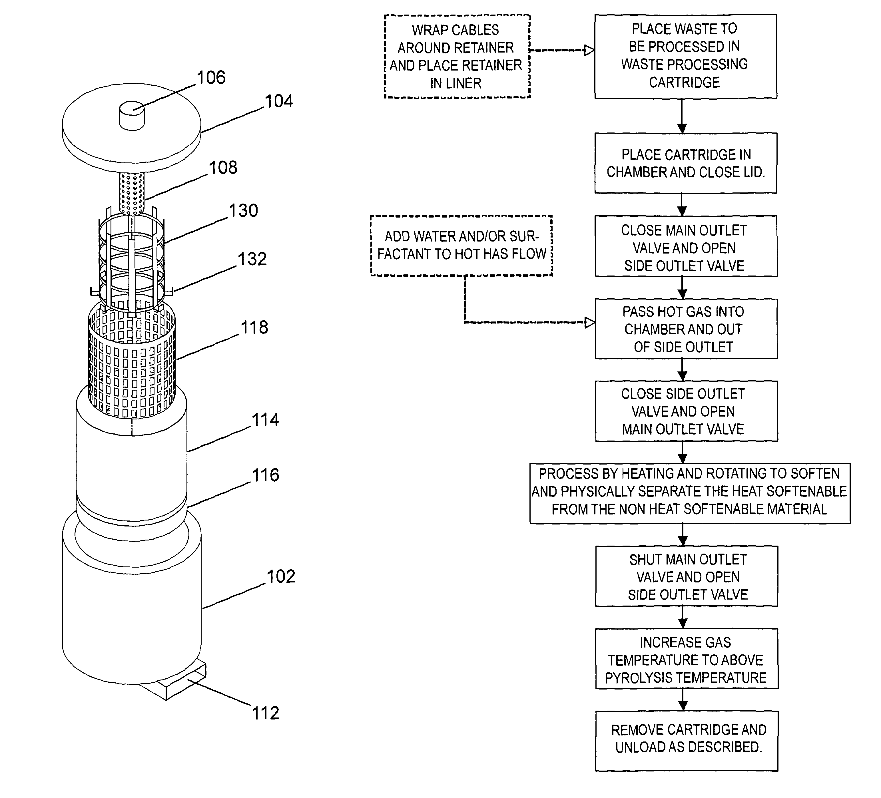
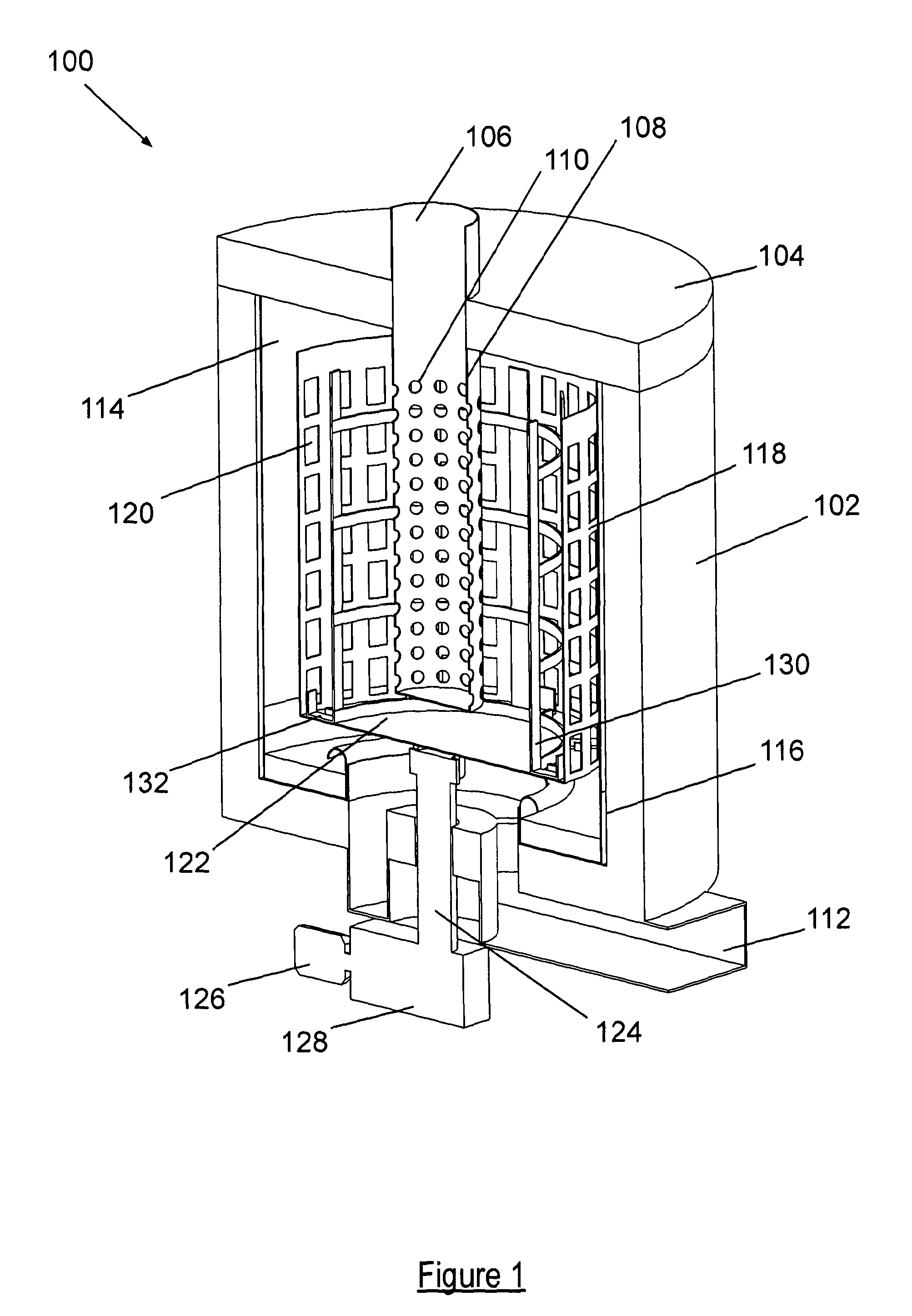
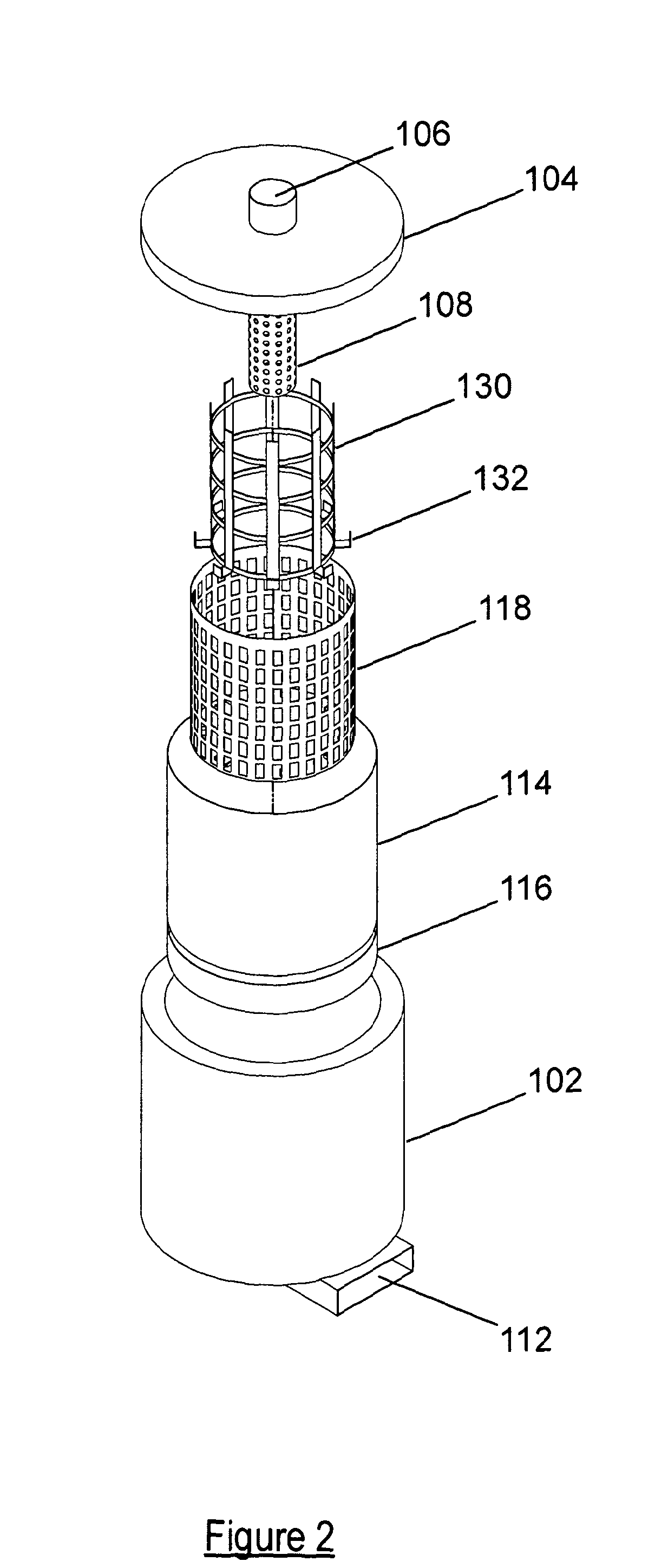
[0042]Referring to FIGS. 1 and 2 an apparatus 100 for processing waste material is shown. The apparatus comprises a heat proof chamber 102 having a lid 104, the chamber and lid defining an interior space in which the waste can be processed. The chamber is preferably of a refractory lined material, although other materials capable of withstanding the process temperatures may of course be used. Located in the lid 104 is an inlet 106 for receiving hot gasses which are used to heat the interior of the chamber. A substantially tubular inlet conduit 108 extends from the inlet into the interior of the chamber 102 substantially along its central axis. The conduit 108 has a closed end and a plurality of perforations 110 in its sides evenly spaced about its circumference.

[0043]An outlet 112 is located at the bottom of the chamber through which hot gasses can exit the apparatus 100. The outlet exits the chamber 102 substantially about its central axis. Located within the chamber is a chamber l...


PUM

PropertyMeasurementUnit
temperatureaaaaaaaaaa
heat softenedaaaaaaaaaa

Abstract

An apparatus (100) for processing waste material is provided which comprises a heat proof chamber (102), a hot gas inlet (106, 112) for heating the interior of the heat proof chamber (102), and a rotatable drum (118) for containing waste to be processed. The drum (118) has gaps (120) therein, is located within the heat proof chamber (102), and separated therefrom around its edge by a gap. The apparatus (100) is also provided with a drive (126, 128) for rotating the drum (118) at a speed such that, in use, waste material that is heat softened is centrifugally separated from the remainder of the waste and passes through the gaps (120) in the drum (118).

Description

CROSS-REFERENCE TO RELATED APPLICATIONS[0001]The present application claims priority to International Application No. PCT / GB2011 / 001310 which was filed on Sep. 7, 2011, and claims priority to the Great Britain Patent Application No. 1018586.6 filed Nov. 4, 2010.STATEMENT RE: FEDERALLY SPONSORED RESEARCH / DEVELOPMENT[0002]Not ApplicableBACKGROUND OF THE INVENTION[0003]The present invention relates to improvements in waste processing, in particular the invention relates to the processing of waste material containing a polymer metal mix, for example waste insulated electrical cable.[0004]With diminishing resources and an increasing cost of oil it is becoming increasingly important that materials are recycled and not put into landfill. Furthermore it is increasingly important that waste materials are processed locally and are not, for example, shipped overseas where they can be disposed of in regimes having less harsh statutory requirements relating to pollution and the processing of was...

Claims


Application Information

Patent Timeline
Patent Type & Authority Patents(United States)
IPC IPC(8): F26B3/02
CPCB29B17/02B29B2017/0255B29B2017/0496C10B57/08B29L2031/3462H01B15/003C10B49/02C10B7/14F26B3/02B29B2017/0231C10B53/00C10B1/10Y02W30/622Y02W30/625Y02W30/821Y02W30/62Y02W30/82B04B1/00B04B3/00B04B15/02
Inventor PERRY, OPHNEIL HENRYCHALABI, RIFAT AL
Owner CHINOOK END STAGE RECYCLING
Why Eureka
Try Eureka