Apparatus for monitoring of grinding mill interior during operation

a technology for monitoring equipment and grinding mills, applied in the field of equipment for monitoring equipment and grinding mill interior during operation, can solve problems such as potential safety risks, large amount of heat released, and long process tim

Active Publication Date: 2019-09-10
MILLWATCHIP
View PDF10 Cites 3 Cited by
  • Summary
  • Abstract
  • Description
  • Claims
  • Application Information

AI Technical Summary

Benefits of technology

[0052]The liquid may include some solid material to provide a slight abrasive action to the screen to assist in cleaning the screen.
[0057]The screen may also be protected by a protective grid or mesh which is fixed or hinged and which contains openings small enough to prevent damage to the screen by larger material (e.g. ore bodies) in the mill but still enabling the monitoring device to monitor the interior of the mill.

Problems solved by technology

During the grinding process, a large amount of heat is released.
It is also a physically involved activity and the whole process often takes several hours due to the work required as well as the safety procedures that must be implemented.
Any time the feed chute is retracted there are potential safety risks.
A grinding mill is a confined space which also brings safety risks.
These risks are increased within a grinding mill due to the unstable environment.
The surface is wet and uneven, making it difficult to walk on.
As the mill cools, the grinding media (steel balls) can explode.
Rocks and balls can become stuck in the liners around the mill and these can dislodge and fall on personnel entering the mill.
This is a time consuming process and only allows limited viewing ability.
Additionally, the area around the mill can be quite hazardous to operators and it is therefore not considered desirable to have an operator in close proximity to the mill for the purposes of viewing.
The cost of such downtime is often hundreds of thousands of dollars of lost production.
Another disadvantage with existing inspection techniques is that real time observations cannot be made while the mill is in operation to immediately observe any potentially adverse conditions.
One reason for this is the extremely hostile conditions inside the mill.
The interior of the mill, as mentioned above, comprises extremely hostile conditions and any monitoring device merely placed inside the mill will almost certainly be pulverised or damaged beyond repair.

Method used


Image

  • Apparatus for monitoring of grinding mill interior during operation
  • Apparatus for monitoring of grinding mill interior during operation
  • Apparatus for monitoring of grinding mill interior during operation

Examples


Embodiment Construction

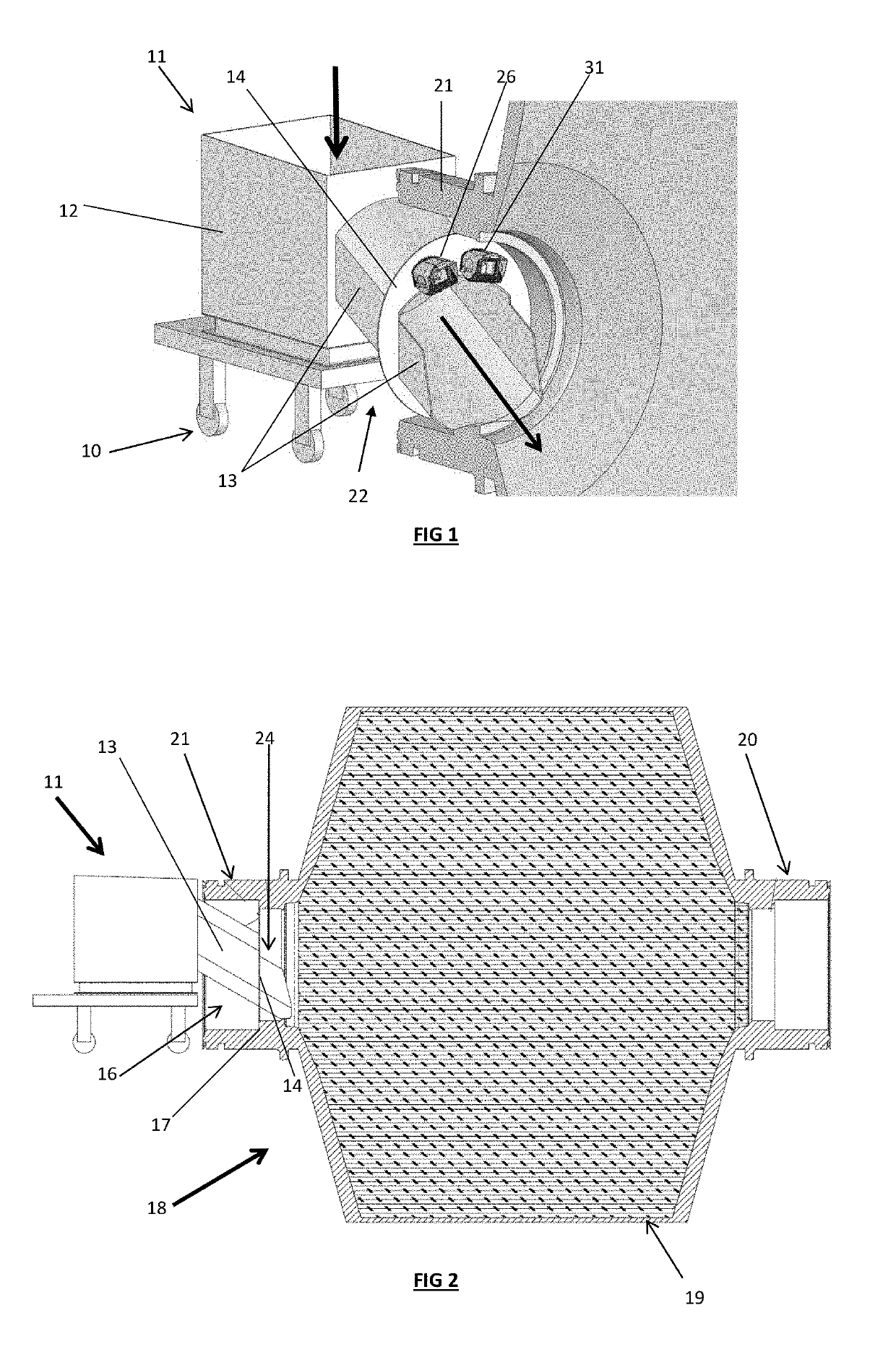
[0115]Referring initially to FIG. 1, there is illustrates a feed chute 11 generally of known design. The feed chute typically comprises a trolley assembly 10 on which an open topped box like arrangement 12 is supported. The box communicates with an outlet assembly 22 that has a chute-like elongate outlet 13. Material to be ground can be dumped into the open box 12 and will pass along the elongate outlet 13 into the grinding body (see FIG. 2). The outlet assembly 22 further comprises an outwardly extending protective surround flange 14 which is disposed about the elongate outlet 13. In use the flange 14 locates against or close to the walls surrounding the inlet that opens into the grinding body to prevent material falling back out of the inlet.

[0116]FIG. 2 illustrates a section view of a SAG mill particularly suited to the present invention. In FIG. 2, the SAG mill 18 has a main cylindrical body 19 in which material is ground. The main cylindrical body 19 rotates about its longitudi...


PUM


Abstract

A monitoring device in the form of a camera in a protective housing is fixed to an outlet assembly of a feed chute and in a particular embodiment to a flange that extends outwardly about an outlet of the outlet assembly. The flange also supports a light also in a protective housing. The feed chute feeds ore into a grinding mill. The housings for the camera and light contain a viewing window which is cleaned by water jets and the window is protected by a visor which can be opened when the interior of the mill is to be recorded. The arrangement allows the interior of the mill to be monitored while the mill is grinding the ore.

Description

TECHNICAL FIELD[0001]The present invention is directed to improvements in the ability to monitor the inside of a grinding mill during operation. The invention is particularly suited to large ball mills used to grind ore. The invention will be described with reference to a ball mill but it should be appreciated that the invention may find suitability with other grinding mills.BACKGROUND[0002]Any references to methods, apparatus or documents of the prior art are not to be taken as constituting any evidence or admission that they formed, or form part of the common general knowledge.[0003]SAG and ball mills are known types of grinding mills that are used to grind ores to smaller sizes. The mill typically comprises a main grinding body in the form of a rotating cylinder which is partially filled with balls, usually stone or metal, which grinds material to the necessary fineness by friction and impact with the tumbling balls. The cylinder has an entry inlet at one end and a discharge outl...

Claims


Application Information

Patent Timeline
Patent Type & Authority Patents(United States)
IPC IPC(8): H04N5/225B02C23/02B02C25/00B02C17/18G06T7/00G03B17/08H04N7/18G03B15/00G03B17/02
CPCH04N5/2252B02C17/183B02C17/1805B02C23/02B02C25/00G03B17/02G06T7/0004H04N7/183G03B15/00G06T2207/30164G03B17/08H04N23/51
Inventor SHAW, JOHNBESTMANN, ROWANCOKER, RICKKINGDON, GREG
Owner MILLWATCHIP
Why Eureka
Try Eureka