
Method of filling and sealing an aerosol dispenser

a dispenser and aerosol technology, applied in the field of aerosol dispensers, can solve the problems of metal containers being undesirable, unable to meet the needs of customers, etc., and achieve the effect of improving the service life and reducing the cost of production

Active Publication Date: 2014-10-28
PROCTER & GAMBLE CO
View PDF26 Cites 133 Cited by
  • Summary
  • Abstract
  • Description
  • Claims
  • Application Information

AI Technical Summary

Benefits of technology

The invention is a method for pressurizing an aerosol dispenser container by using a pressurizeable outer container, a valve cup, and a manifold. The method involves applying a manifold with a supply of propellant to the outer container, dispensing the propellant into the container to internally pressurize it, sealing the container to keep the propellant at atmospheric pressure, and then removing the manifold. The technical effect is a more efficient and effective pressurization process for aerosol dispenser containers.

Problems solved by technology

However, metal containers can be undesirable due to high cost and limited recyclability.
The dip tube embodiment of an aerosol dispenser has the disadvantage that when the user tips the aerosol dispenser from a vertical orientation, dispensing of gas from the headspace, rather than dispensing of product / propellant mixture, may occur.
This disadvantage may occur when the aerosol dispenser contains a product such as a body spray, which the user dispenses all over his / her body, often from inverted positions.
The process for manufacturing a bag on valve type aerosol dispenser is complicated.
If a hydrocarbon propellant is selected, the manufacturing process becomes more complex and costly due to safety concerns, environmental regulations and other industry regulations.
Propellant filling of aerosol dispensers presents its own challenges.
However, utilizing a common site for pressurization and filling of the aerosol dispenser presents certain problems and inherent fixed costs.
For example, each manufacturing site must have the complex and highly regulated propellant pressurizing equipment and safety systems.
A single manufacturing site may not be able to quickly respond to changes in consumer preference or to tailor the product to the unique consumer preferences in different geographies.

Method used


Image

  • Method of filling and sealing an aerosol dispenser
  • Method of filling and sealing an aerosol dispenser
  • Method of filling and sealing an aerosol dispenser

Examples


Embodiment Construction

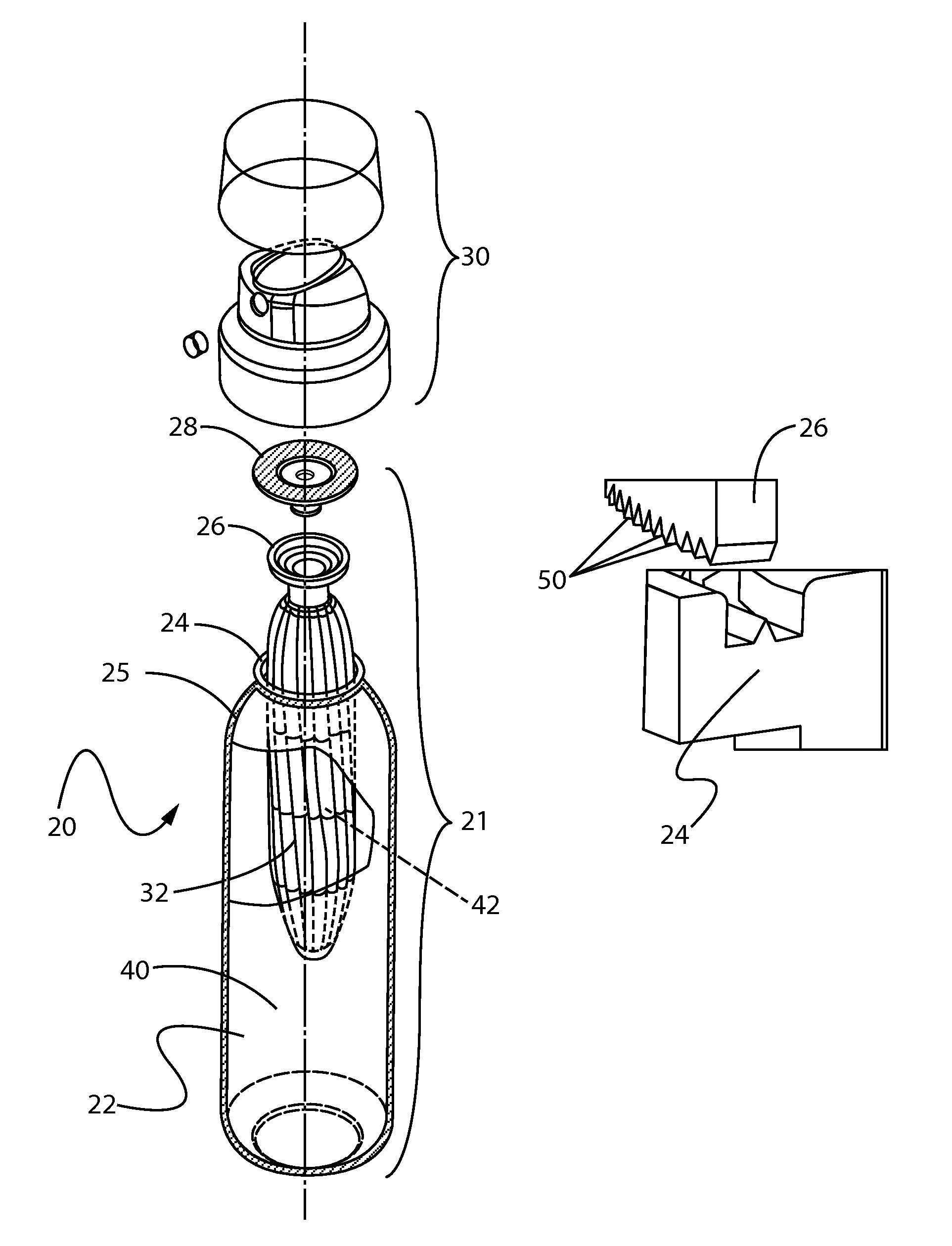
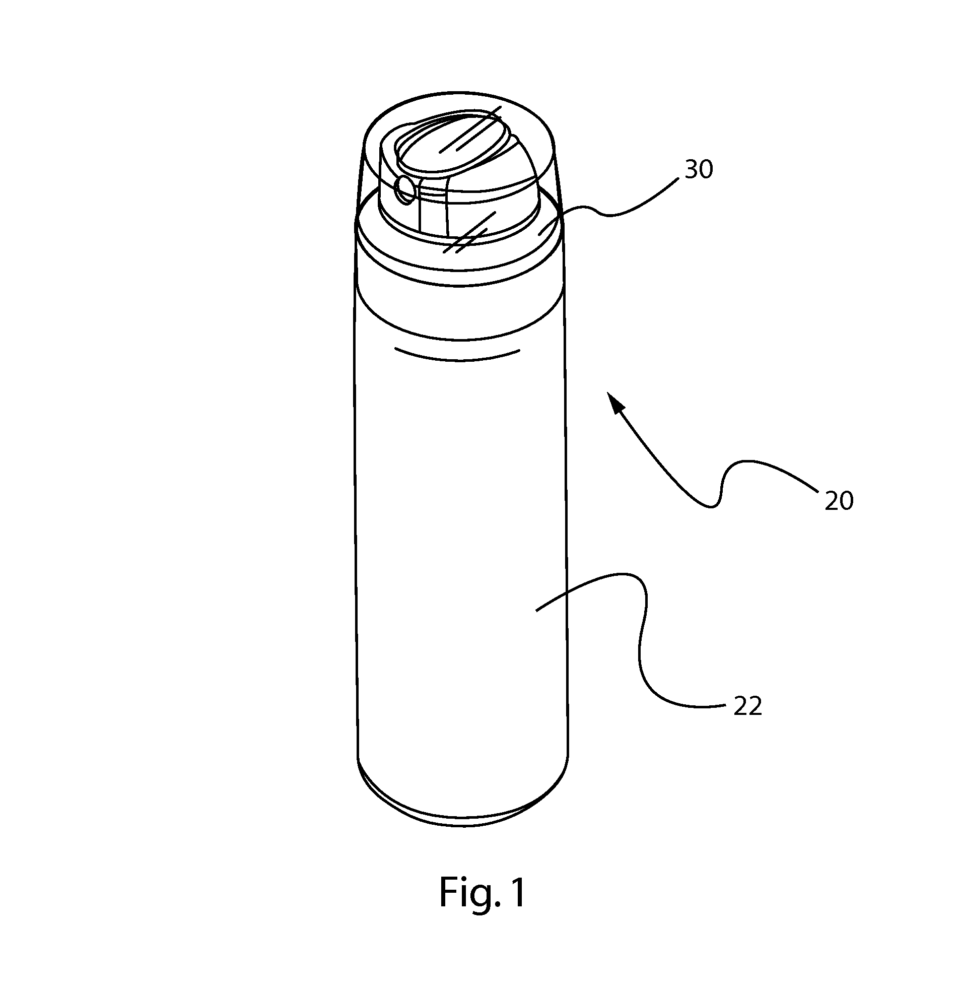
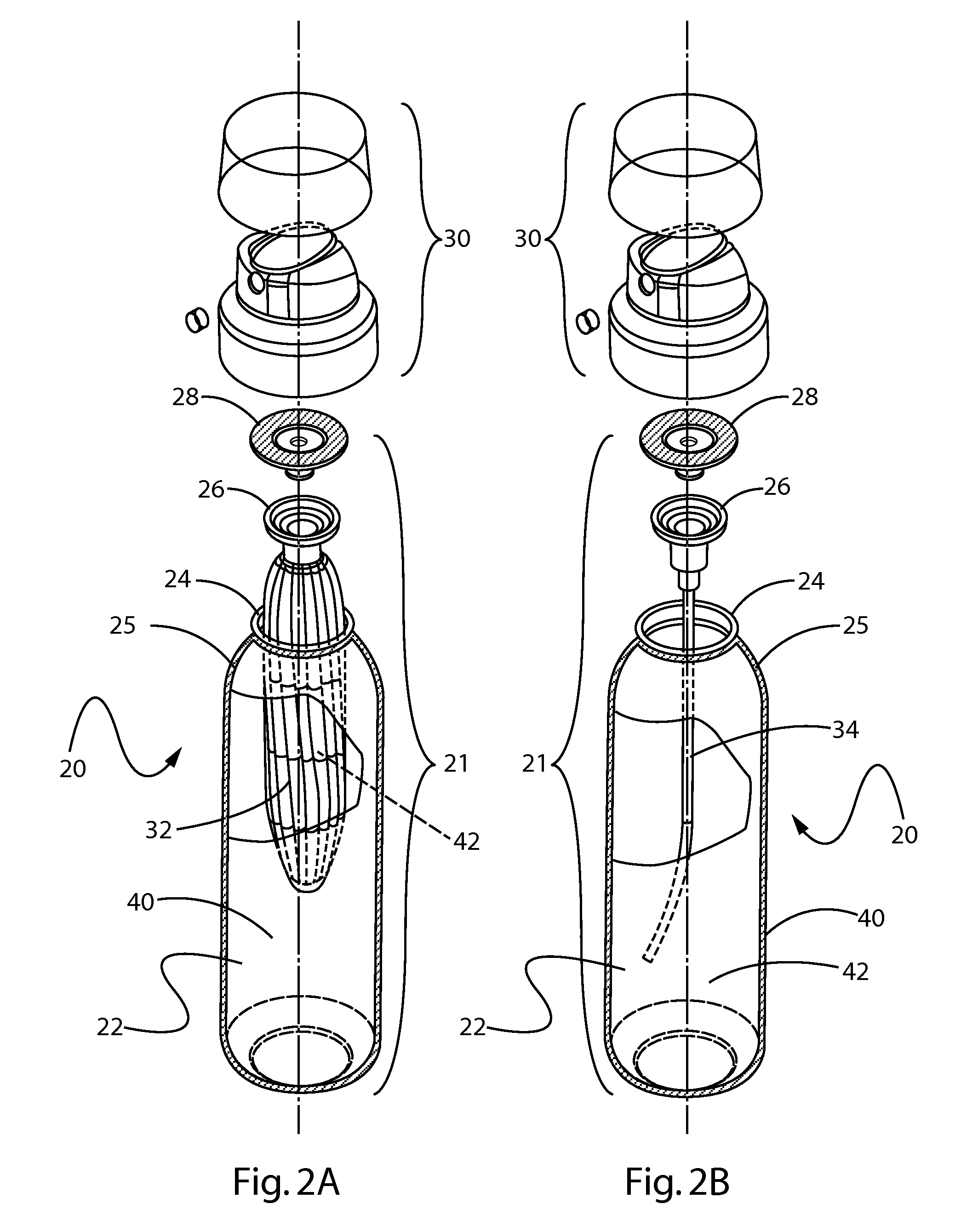
[0031]Referring to FIGS. 1, 2A and 2B, an aerosol dispenser 20 is shown. The aerosol dispenser 20 comprises a pressurizeable outer container 22 usable for such a dispenser. The outer container 22 may comprise plastic or metal, as are known in the art. The outer container 22 may have an opening. The opening is typically at the top of the pressurizeable container when the pressurizeable container is in its-in use position. The opening defines a neck 24, to which other components may be sealed.

[0032]A valve cup 26 may be sealed to the opening of the outer container 22, as described in further detail below. A valve assembly 28, in turn, may be disposed within the valve cup 26. The valve assembly 28 provides for retention of product 42 within the aerosol dispenser 20 until the product 42 is selectively dispensed by a user. The valve assembly 28 may be selectively actuated by an actuator 30. Neither the valve assembly 28 nor the actuator 30 form any part of the claimed invention.

[0033]Sel...


PUM

PropertyMeasurementUnit
pressureaaaaaaaaaa
pressureaaaaaaaaaa
diametersaaaaaaaaaa

Abstract

A method of pressurizing a container usable for an aerosol dispenser. The method comprises providing a pressurizeable outer container and complementary valve cup, at least one having a channel into the container. A manifold is brought into sealing relationship with the channel of the container. Propellant is supplied from the manifold, goes through the channel and into the container. While the manifold is still sealed to the container, the channel is sealed shut to maintain the pressure. Sealing may be accomplished by sonic or ultrasonic welding.

Description

FIELD OF THE INVENTION[0001]The present invention relates to aerosol dispensers and the manufacture of components thereof.BACKGROUND OF THE INVENTION[0002]Aerosol dispensers are well known in the art. Aerosol dispensers typically comprise an outer container which acts as a frame for the remaining components and as a pressure vessel for propellant and product contained therein. Outer containers made of metal are well known in the art. However, metal containers can be undesirable due to high cost and limited recyclability.[0003]The outer containers are typically, but not necessarily, cylindrical. The outer container may comprise a bottom for resting on horizontal surfaces such as shelves, countertops, tables etc. The bottom of the outer container may comprise a re-entrant portion as shown in U.S. Pat. No. 3,403,804. Sidewalls defining the shape of the outer container extend upwardly from the bottom to an open top.[0004]The open top defines a neck for receiving additional components of...

Claims


Application Information

Patent Timeline
Patent Type & Authority Patents(United States)
IPC IPC(8): B65B3/04B65B31/00B65D83/62B05B9/08
CPCB65B31/003B05B9/0838B65D83/62B65D83/425B65B61/26B65D83/38B65B31/025B65D77/065B65D83/0005B65D35/22B65B3/045
Inventor SMITH, SCOTT, EDWARD
Owner PROCTER & GAMBLE CO
Learn More