Connector with connecting members held by a beam supported by a supporting member
a technology of connecting member and supporting member, which is applied in the direction of coupling contact member, coupling device connection, securing/insulating coupling contact member, etc., can solve the problem of hindering the pitch narrowing of the conductor 124 in the third direction z, suppress the offset in the position of the conductive portion, and improve the contact reliability of the connector
- Summary
- Abstract
- Description
- Claims
- Application Information
AI Technical Summary
Benefits of technology
Problems solved by technology
Method used
Image
Examples
first embodiment
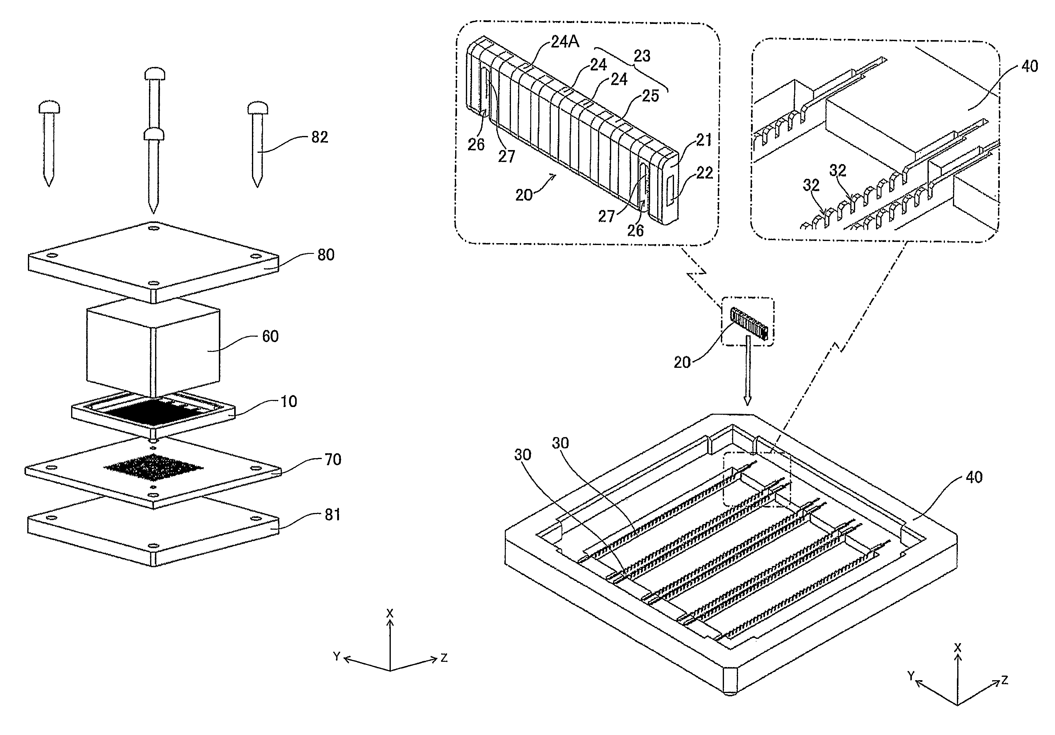
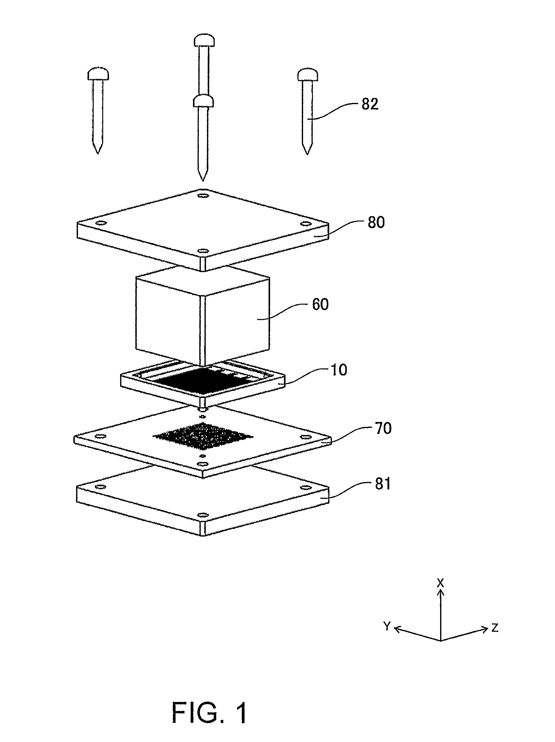
[0040]As shown in FIG. 1, a connector 10 according to this invention is adapted to be interposed between a first connection object 60 formed as an IC package and a second connection object 70 formed as a lower board, thereby establishing electrical connection between the first and second connection objects 60 and 70. In FIG. 1, numeral 80 denotes an upper stiffener, numeral 81 denotes a lower stiffener, and numeral 82 denotes screws for fixing the upper and lower stiffeners 80 and 81 together. While the connector 10 is described as an actual mounting connector in this embodiment, it may alternatively be used as an inspection connector.
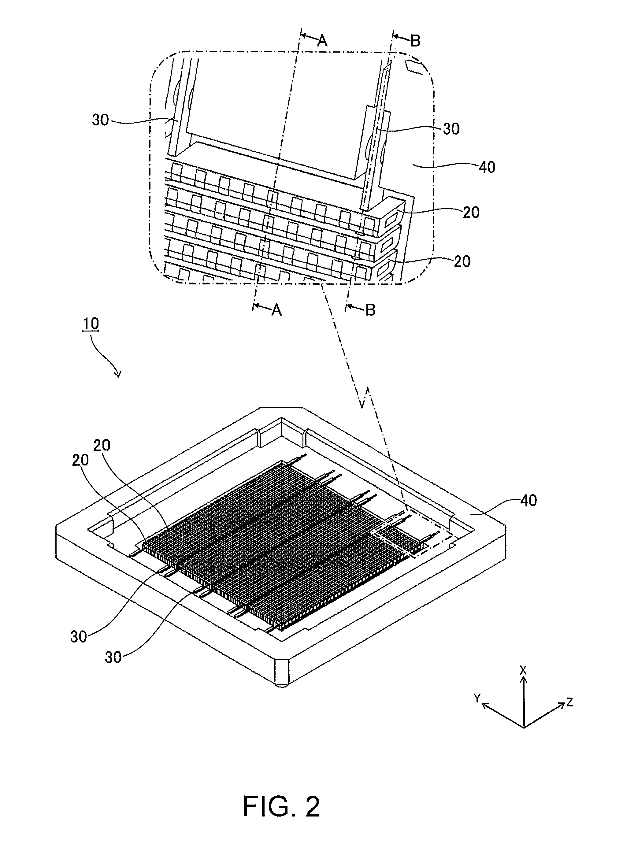
[0041]As shown in FIGS. 2 to 4, the connector 10 comprises a plurality of connecting members 20, a plurality of beams 30 holding the connecting members 20, and a frame 40 supporting the beams 30.
[0042]As shown in FIG. 2, the connecting members 20, each having a longitudinal direction extending in the second direction Y, are arranged in the third direct...
third embodiment
[0063]In the third embodiment, as shown in FIGS. 9 and 10, pressing members 50 are further provided for preventing connecting members 20 from coming off. As shown in FIG. 10, each pressing member 50 is disposed with its longitudinal direction extending in the third direction Z so as to perpendicularly cross the connecting members 20 and is arranged on the side opposite to beams 30 in the first direction X with respect to the connecting members 20. As shown in FIG. 10, both ends in the longitudinal direction of the pressing member 50 are respectively inserted in the first direction X into pressing member grooves 47 formed on a frame 40 so that frame engaging portions 51 formed at both ends in the longitudinal direction of the pressing member 50 engage with the frame 40. Consequently, the pressing member 50 is detachably attached to the frame 40.
[0064]In the third embodiment, as shown in FIGS. 9 and 10, each connecting member 20 has a cutout-like pressing member receiving portion 28 a...
PUM
 Abstract
Description
Claims
Application Information
 - R&D
- Intellectual Property
- Life Sciences
- Materials
- Tech Scout
- Unparalleled Data Quality
- Higher Quality Content
- 60% Fewer Hallucinations
Browse by: Latest US Patents, China's latest patents, Technical Efficacy Thesaurus, Application Domain, Technology Topic, Popular Technical Reports.
© 2025 PatSnap. All rights reserved.Legal|Privacy policy|Modern Slavery Act Transparency Statement|Sitemap|About US| Contact US: help@patsnap.com


