Method and controller for an electric motor with fault detection

a technology of fault detection and electric motor, which is applied in the direction of electronic commutation motor control, motor/generator/converter stopper, dynamo-electric converter control, etc., can solve problems such as motors being susceptible to damage, and achieve the effect of preventing demagnetization of permanent magnets

Active Publication Date: 2014-10-28
DEERE & CO
View PDF24 Cites 16 Cited by
  • Summary
  • Abstract
  • Description
  • Claims
  • Application Information

AI Technical Summary

Benefits of technology

[0003]In accordance with one embodiment, a method and system is presented for fault detection or prevention in a controller for an electric motor. For each phase of a controller, a pair of semiconductor switches comprises a high side switch and a low side switch. A direct current voltage bus provides electrical energy to the semiconductor switches (e.g., switchably via a direct current power switch). A measuring circuit is adapted to measure the collector-emitter voltage or drain-source voltage for each semiconductor switch of the controller. A data processor determines that a short circuit in a particular semiconductor switch is present if the measured collector-emitter voltage or measured source-drain voltage for the particular semiconductor switch is lower than a minimum threshold (e.g., during a commanded off-state of the particular semiconductor switch or over at least one complete cycle or waveform of an inverter driver signal) and if an observed current associated with the particular semiconductor switch has an opposite polarity from a normal operational polarity. A driver simultaneously activates counterpart switches of like direct current input polarity that are coupled to other phase windings of the electric motor, other than the particular semiconductor switch, to protect the electric motor from potential damage associated with asymmetric current flow (e.g., prevent demagnetization of the permanent magnets in the electric motor).

Problems solved by technology

The asymmetric current makes the motor susceptible to damage, such as demagnetization of one or more permanent magnets within the motor (e.g., or its rotor).

Method used


Image

  • Method and controller for an electric motor with fault detection
  • Method and controller for an electric motor with fault detection
  • Method and controller for an electric motor with fault detection

Examples


Embodiment Construction

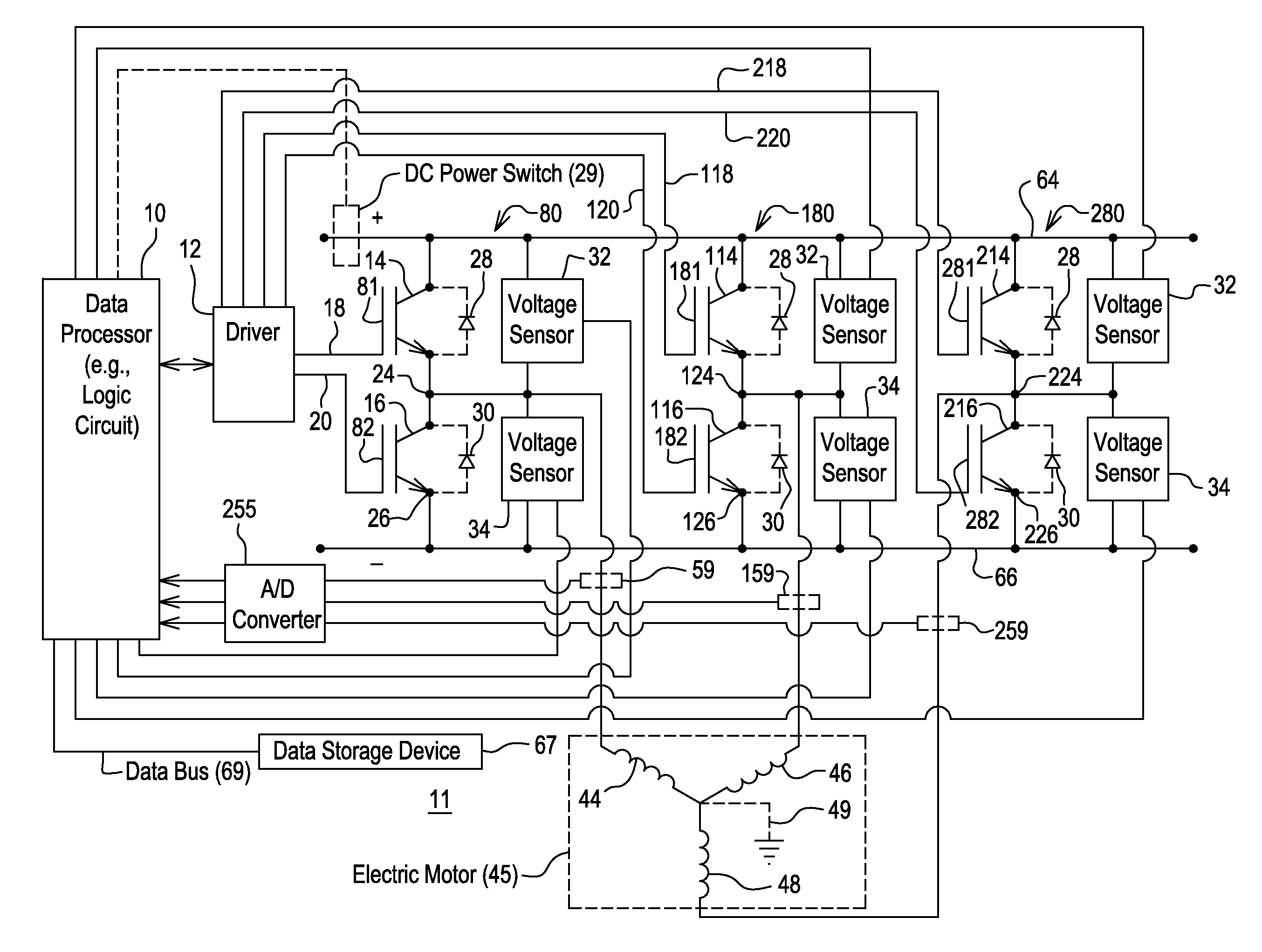
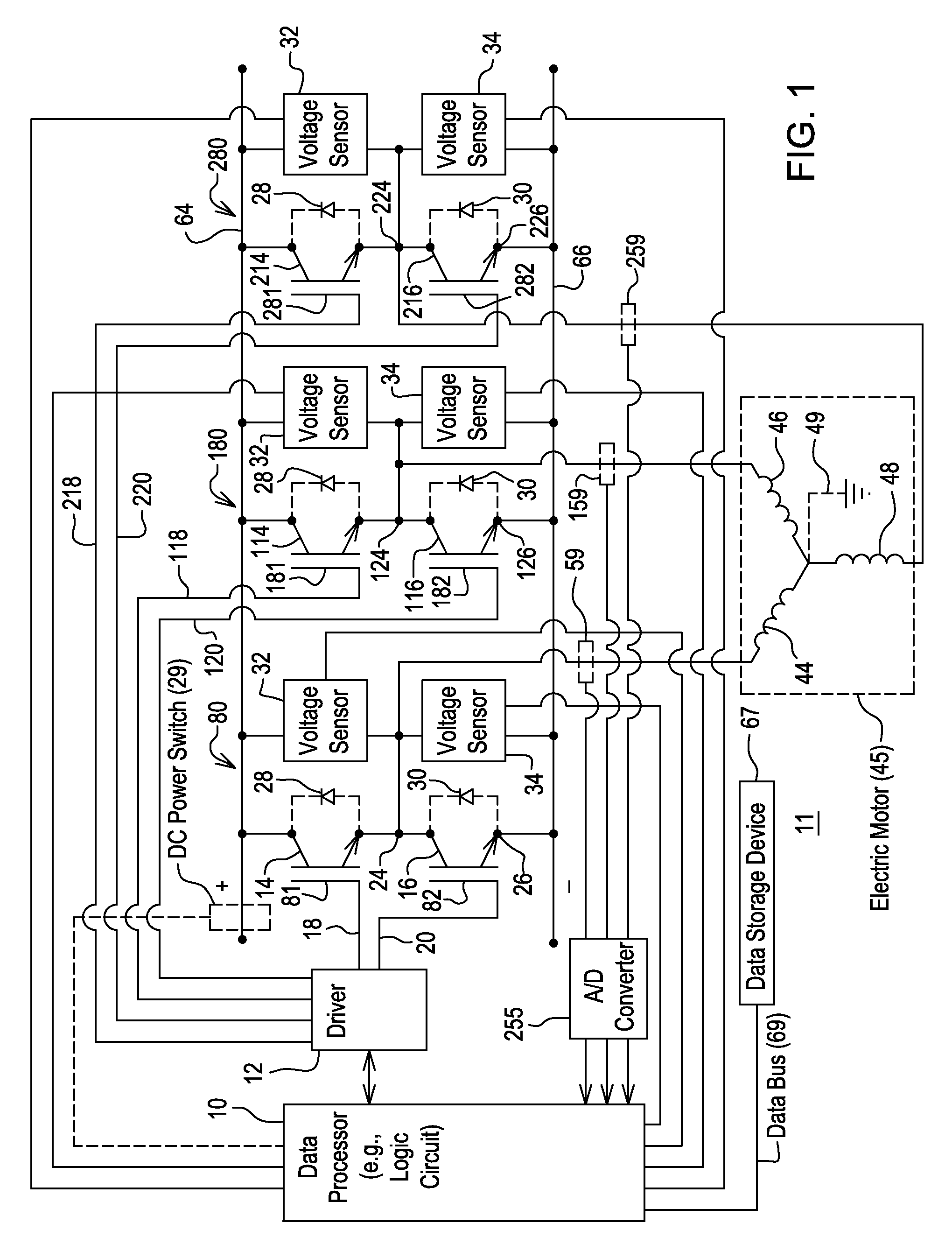
[0013]An asymmetric current flow in the windings (44, 46, and 48) of a motor 45 refer to a condition where a direct current (e.g., positive current or negative current) or direct current offset from one or more direct current terminals (64, 66) is continuously applied to only one winding (44, 46, or 48) or one phase of the motor 45. The asymmetric current flow may be referred to as an unbalanced current flow. For example, the asymmetric current flow may result from a fault or short circuit in a single semiconductor switch of an inverter or controller. For certain motor 45 designs, an asymmetric current flow or unbalanced current flow may place the one or more motor windings (44, 46, or 48) under thermal stress, may partially demagnetize permanent magnets of the motor 45 over an extended period of time, or may make the motor 45 susceptible to reduced longevity, among other things. For example, the continuous input of direct current or a direct current offset to a winding (44, 46, or ...


PUM


Abstract

For each phase of a controller, semiconductor switches comprise a high side switch and a low side switch. A direct current voltage bus provides electrical energy to the semiconductor switches. A measuring circuit is adapted to measure the collector-emitter voltage or drain-source voltage for each semiconductor switch of the controller. A data processor determines that a short circuit in a particular semiconductor switch is present if the measured collector-emitter voltage or measured source-drain voltage for the particular semiconductor switch is lower than a minimum threshold and if an observed current associated with the particular semiconductor switch has an opposite polarity from a normal operational polarity. A driver simultaneously activates counterpart switches of like direct current input polarity that are coupled to other phase windings of the electric motor, other than the particular semiconductor switch, to protect the electric motor from potential damage associated with asymmetric current flow.

Description

FIELD OF THE INVENTION[0001]This invention relates to a method and controller for electric motor with fault detection.BACKGROUND OF THE INVENTION[0002]An electric motor may feature a rotor with permanent magnets and a stator, such as an interior permanent magnet (IPM) motor or an IPM synchronous motor. In accordance with certain prior art, an inverter or motor controller comprises semiconductor switches that support the provision of alternating current outputs for one or more phases of the electric motor. A short circuit, which appears across the output terminals of one semiconductor switch, may cause an asymmetric current to flow in the windings of an electric motor. The asymmetric current makes the motor susceptible to damage, such as demagnetization of one or more permanent magnets within the motor (e.g., or its rotor). Thus, there is a need for an improved method and controller for an electric motor with fault detection.SUMMARY OF THE INVENTION[0003]In accordance with one embodi...

Claims


Application Information

Patent Timeline
Patent Type & Authority Patents(United States)
IPC IPC(8): H02P6/12H02P23/00H02M7/5387
CPCH02P29/022H02P29/027H02M1/32H02M7/53871H02M7/53873H02P29/0241
Inventor TREMEL, CHRIS JVILAR, ERIC
Owner DEERE & CO
Why Eureka
Try Eureka