Method and mould arrangement for explosion forming

a technology of explosive forming and tool arrangement, which is applied in the direction of metal-working apparatus, etc., can solve the problems of cost and time-consuming methods, and achieve the effect of method and tool arrangement, suitable for mass production

Active Publication Date: 2014-11-04
MAGNA INTERNATIONAL INC
View PDF102 Cites 5 Cited by
  • Summary
  • Abstract
  • Description
  • Claims
  • Application Information

AI Technical Summary

Benefits of technology

[0004]The object of the present invention is to improve a method and a tool arrangement for explosive forming of the kind mentioned at the beginning to the effect that the method and the tool arrangement are simplified and suitable for mass production.

Problems solved by technology

This method is, however, costly and time-consuming.

Method used


Image

  • Method and mould arrangement for explosion forming
  • Method and mould arrangement for explosion forming
  • Method and mould arrangement for explosion forming

Examples


first embodiment

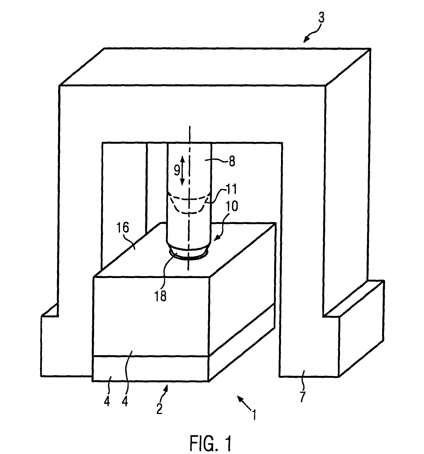
[0036]FIG. 1 shows a perspective view of a tool arrangement 1 according to the invention in accordance with the invention. The tool arrangement 1 in this embodiment comprises a moulding tool 2 and an ignition aggregate 3.

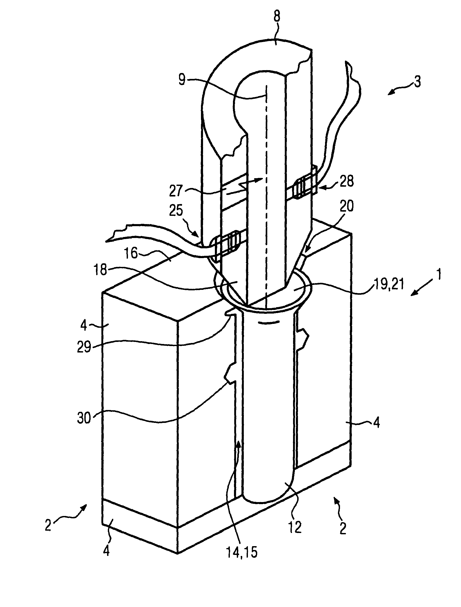
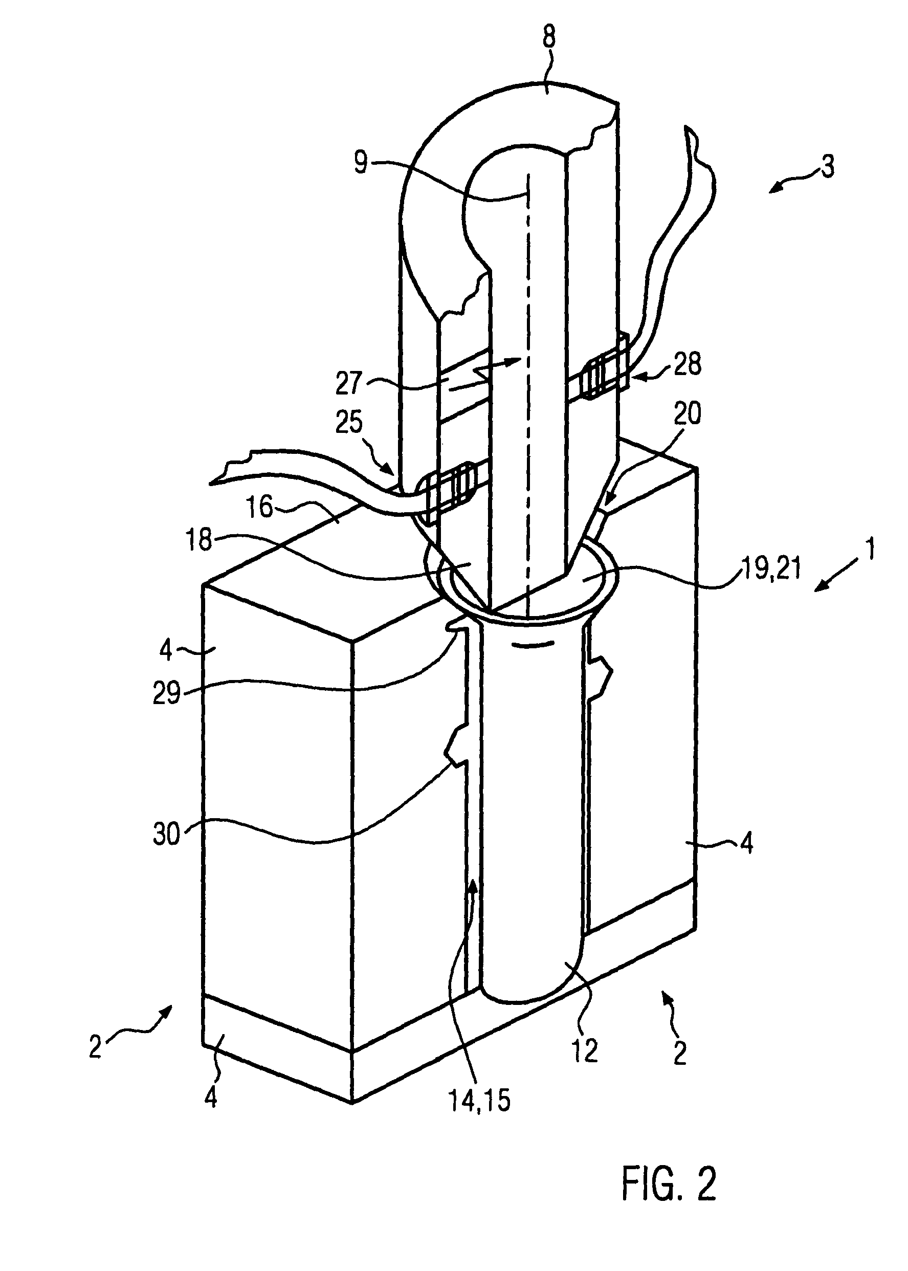
[0037]The moulding tool 2 is formed in a multiple number of pieces. It consists of a multiple number of mould halves 4, which can be assembled into the moulding tool 2. When closed, which means when all mould tool halves 4 are assembled together, a mould cavity 14 results in the interior of the moulding tool 2, whereby the contour of this mould cavity 14 produces the later shape of the completed workpiece. In addition, cutting or separating edges 29 and matrices of holes 30 can be provided in the contour of the moulding tool 2, in order to simultaneously cut the workpiece during the explosive forming, as shown in FIGS. 3 to 5. The mould cavity 14 simultaneously forms an intake area 15 of the moulding tool 2. According to the invention, the intake area 15 is at least...

second embodiment

[0049]FIG. 4 shows a cut through a tool arrangement 1 according to the invention in accordance with the invention. The reference numbers used in FIG. 4 indicate the same parts as in FIGS. 1 to 3, so that reference is made to the description for FIGS. 1 to 3 in this regard.

[0050]In FIG. 4, the intake area 15 or the workpiece cavity 13 is completely filled with the liquid. The explosive gas mixture 23 here is again located above the surface of the liquid 22. The gas connection 25 is located below the surface of the liquid 22 in this embodiment. It is arranged here in one of the moulding tool halves 4.

[0051]FIG. 5 shows a cut through the tool arrangement 1 according to the invention as shown in FIG. 4, but with a changed liquid level. The reference numbers used in FIG. 5 indicate the same parts as in FIGS. 1 to 4, so that reference is made to the description of FIGS. 1 to 4 in this regard.

[0052]The workpiece cavity 13 here is completely filled with liquid 26. The workpiece holding area...


PUM

PropertyMeasurementUnit
pressureaaaaaaaaaa
pressureaaaaaaaaaa
pressureaaaaaaaaaa

Abstract

The invention is intended to improve a tool arrangement and method for explosive forming of a workpiece by means of gas explosion, in which the workpiece is arranged in a intake area of a molding tool, wherein the intake area is at least partially filled with liquid and the explosion is triggered by means of ignition of an explosive gas mixture, to the effect that the tool arrangement and the method are suitable and simplified for mass production. This object is solved by means of a tool arrangement and a method for explosive forming of a workpiece by means of gas explosion, in which the workpiece is arranged in a intake area of a molding tool, wherein the intake area is at least partially filled with liquid and the explosion is triggered by means of ignition of an explosive gas mixture, in which the explosive gas mixture is provided at least partially above the surface of the liquid before the ignition.

Description

CROSS-REFERENCE TO RELATED APPLICATIONS[0001]This application is a national entry application of PCT Application WO 2008 / 098608 filed on Dec. 13, 2007, entitled “Method And Mould Arrangement For Explosion Forming” and claiming priority from German Patent No. 10 2007 007 330 filed on Feb. 14, 2007, entitled “Verfahren and Werkzeuganordnung zum Explosionsumformen” (Method and Tool Arrangement for Explosive Forming), the disclosures of which are incorporated herein by reference for all purposes.FIELD OF THE INVENTION[0002]The invention relates to a method and a tool arrangement for explosive forming.BACKGROUND OF THE INVENTION[0003]In a method of this kind known from CH 409 831, the workpiece to be formed, e.g., a tube, is inserted into a form and filled with water. A device that comprises a multiple number of electrodes and that is intended for generating and igniting a detonating gas is packed in an elastic container, e.g., a plastic bag. This is placed inside the workpiece, sunk so ...

Claims


Application Information

Patent Timeline
Patent Type & Authority Patents(United States)
IPC IPC(8): B21D26/02B21D26/08
CPCB21D26/08Y10S72/706
Inventor ZAK, ALEXANDERKOTAGIRI, SEETARAMA S.STRANZ, ANDREASSTOEGER, PHILIPP
Owner MAGNA INTERNATIONAL INC
Why Eureka
Try Eureka