Aircraft refuelling system
a refuelling system and aircraft technology, applied in the direction of lift valves, valve details, operating means/releasing devices of valves, etc., can solve the problems of reducing aircraft performance and design freedom, increasing pressure, and increasing the weight and size of tanks, so as to increase the refuelling rate
- Summary
- Abstract
- Description
- Claims
- Application Information
AI Technical Summary
Benefits of technology
Problems solved by technology
Method used
Image
Examples
Embodiment Construction
[0044]The embodiment of the invention provides an improved aircraft refuelling system to allow faster refuelling times.
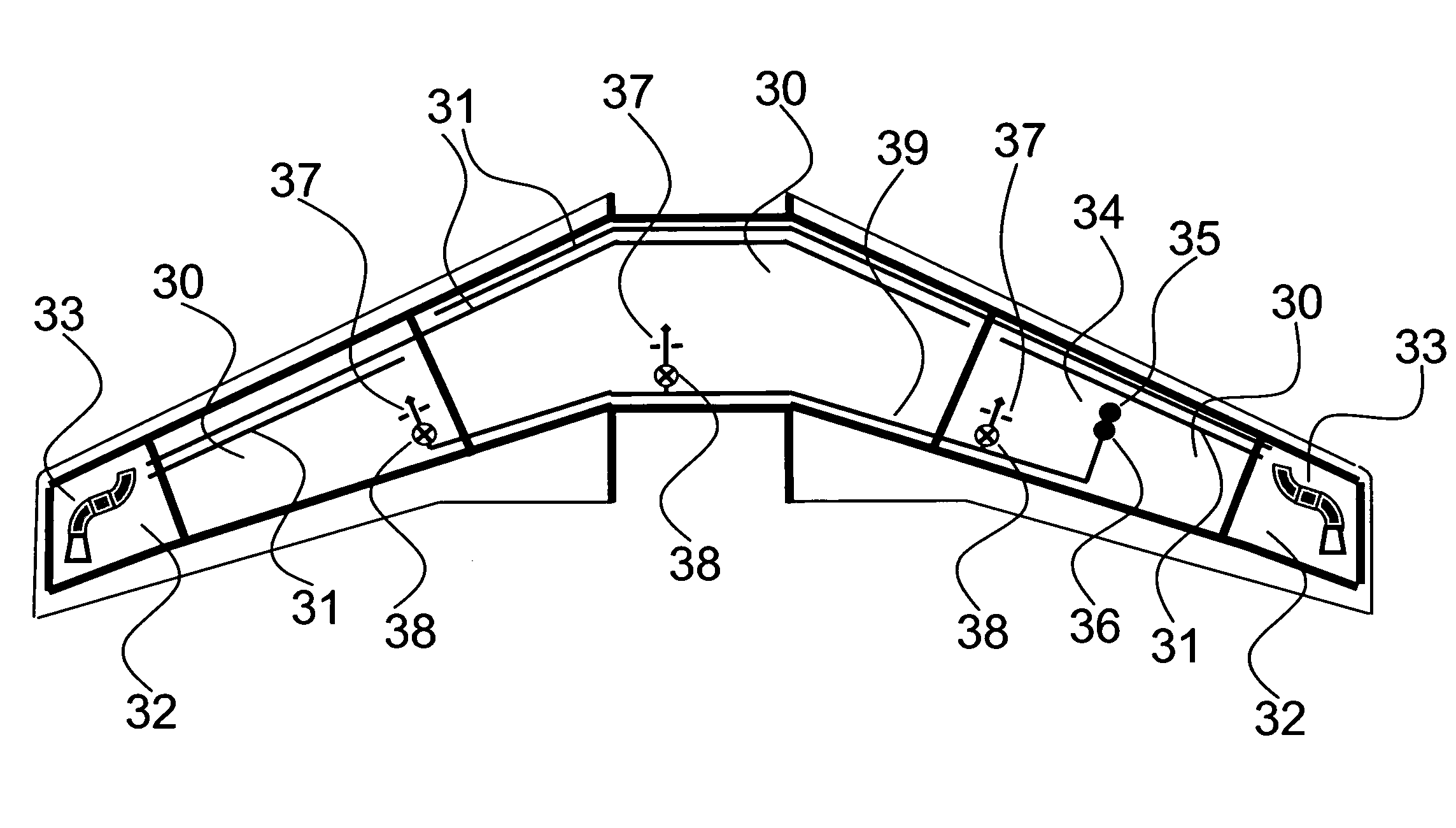
[0045]FIG. 3 is a schematic diagram of an aircraft refuelling system according to an embodiment of the present invention. The aircraft has fuel tanks 30 located in the fuselage and wings, which tanks are connected to vent pipework 31 to allow air (or inert gas) to flow out of the tanks 30. In the case of fuel overflow, fuel may be caused to flow through the vent pipework 31 as it is forced out of the fuel tanks 30. Two vent pipes are provided for the centre tank, each having an inlet at one side of the centre tank and an outlet to the vent tank located on the opposite side of the aircraft to the inlet. The vent pipework 31 is open to vent tanks 32 such that fuel passing through the vent pipework during an overflow is caught by the vent tanks 32. The pipework also vents to the exterior of the aircraft via flame arrestors 33 to allow air to escape from the fuel tanks ...
PUM
 Abstract
Description
Claims
Application Information
 - R&D
- Intellectual Property
- Life Sciences
- Materials
- Tech Scout
- Unparalleled Data Quality
- Higher Quality Content
- 60% Fewer Hallucinations
Browse by: Latest US Patents, China's latest patents, Technical Efficacy Thesaurus, Application Domain, Technology Topic, Popular Technical Reports.
© 2025 PatSnap. All rights reserved.Legal|Privacy policy|Modern Slavery Act Transparency Statement|Sitemap|About US| Contact US: help@patsnap.com


