Systems and methods for beam enhancement

a beam enhancement and beam technology, applied in the field of beam enhancement, can solve the problems of image degradation, inability to meet the nyquist criterion of sampling spacing between beams and scan lines, and often cannot be adopted for ultrasound scanned volume imaging, etc., and achieve the effect of enhancing beam mainlobe attributes

Active Publication Date: 2014-11-04
FUJIFILM SONOSITE
View PDF71 Cites 1 Cited by
  • Summary
  • Abstract
  • Description
  • Claims
  • Application Information

AI Technical Summary

Benefits of technology

[0024]A sharpening function may be applied to DR / IDR beams, if desired, to provide an even further enhanced beam. DR / IDR beams having a sharpening function applied thereto are referred to herein as enhanced dynamic resolution (XDR) beams. XDR beams, having had a sharpening function applied, provide a mainlobe that is narrower than the corresponding DR / IDR beam. Additionally, the sidelobes of such XDR beams can be further suppressed at a level to achieve better image quality.
[0026]One feature of embodiments of the invention is to optimize the focus performance of every beamformed sample in the sample space of a generated image. Another feature of embodiments of the invention is minimizing spectral leakage and improving spectral resolution in pulse wave (“PW”), continuous wave (“CW”), and color flow processing with or without coded excitation and code patterns. A still further feature of the invention is that embodiments may readily be adapted for use in many types of systems, such as multi-line beamforming, synthetic aperture beamforming and high frame rate beamforming.

Problems solved by technology

However, in ultrasound imaging, the line density is selected according to multiple system parameters for optimal image quality, thus setting the sampling spacing from beam to beam or scan line to scan line according to Nyquist criterion generally cannot be satisfied.
Thus, the clutter reduction technique based on processing Sinc beam, such as may be implemented for radar, often cannot be adopted for use in ultrasound scanned volume imaging.
Another source of image degradation is the width of the mainlobes used to collect image information.
Each results in a degradation of image quality and will display a distorted image.
The artifacts associated with the use of beam BU also extend a long distance from corresponding ones of object of interest representations, further degrading the generated image.
Each of the foregoing beam forming techniques, therefore, results in generated images which often are of a lower quality than desired.
As can be appreciated from the foregoing, achieving a well-defined beam without significant sidelobes for providing quality imaging has proven illusive.

Method used


Image

  • Systems and methods for beam enhancement
  • Systems and methods for beam enhancement
  • Systems and methods for beam enhancement

Examples


Embodiment Construction

[0050]FIG. 2A shows an embodiment of an ultrasound imaging system adapted according to an embodiment of the invention. It should be appreciated that the exemplary embodiment is described with reference to ultrasound imaging in order to provide a more concrete example to aid in understanding the concepts herein. However, the concepts of the present invention are not limited to application with respect to ultrasound imaging. Thus, the concepts herein may be applied with respect to a number of technologies wherein reflection of transmitted signals are used, such as visible light, infrared, and radio frequency imaging techniques.

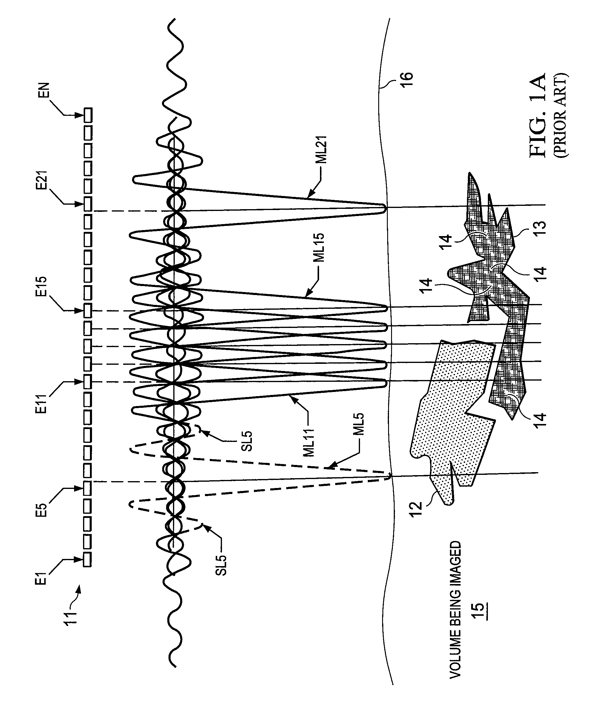
[0051]Ultrasound imaging system 200 is shown comprising system unit 210 in communication with scanhead 220. System unit 210 of embodiments comprises a processor-based system operable to control a transducer (e.g., transducer 11 shown in FIG. 1A) of scanhead 220 to transmit and receive ultrasound signals using scanned beams 221 to provide scanned volume imaging. ...


PUM


Abstract

Beam enhancement through sidelobe reduction and / or mainlobe sharpening is shown. Embodiments utilize dynamic resolution, improved dynamic resolution, and / or enhanced dynamic resolution techniques to synthesize beams, such as ultrasonic beams used in ultrasonic imaging, having desired attributes. Embodiments simultaneously form a first sample beam and a second or auxiliary sample beam for every sample to synthesize enhanced scan beams. According to a dynamic resolution techniques herein a new beam may be formed from the sum of the two sample beams. A synthesized dynamic resolution beam of embodiments has reduced sidelobes with relatively little or no spread of the mainlobe. An enhanced dynamic resolution beam sharpening function can be applied to provide a further enhanced beam, such as to further narrow the mainlobe.

Description

CROSS-REFERENCE TO RELATED APPLICATIONS[0001]This application claims the benefit of U.S. Provisional Patent Application No. 61 / 259,346, entitled “SYSTEMS AND METHODS FOR SCAN BEAM SIDELOBE REDUCTION WHILE REDUCING THE MAINLOBE USING DYNAMIC RESOLUTION”, filed on Nov. 9, 2009; and U.S. Provisional Patent Application No. 61 / 259,938, entitled “SYSTEMS AND METHODS FOR SCAN BEAM SIDELOBE REDUCTION WHILE REDUCING THE MAINLOBE USING DYNAMIC RESOLUTION”, filed on Nov. 10, 2009; the full disclosure of which are incorporated herein by reference.TECHNICAL FIELD[0002]This disclosure relates to beamforming and more particularly to systems and methods for beam enhancement, such as through sidelobe reduction and / or mainlobe shaping.BACKGROUND OF THE INVENTION[0003]In sonographic systems, acoustic signals are transmitted by a scanhead into a body or other subject and reflected signals are received by the scanhead for image processing. The reflected signals are used by the sonographic system to form...

Claims


Application Information

Patent Timeline
Patent Type & Authority Patents(United States)
IPC IPC(8): G01S15/89G10K11/34G01S7/52A61B8/00
CPCG10K11/341G01S15/8977G01S7/52047A61B8/5207G01S7/5208
Inventor HWANG, JUIN, JET
Owner FUJIFILM SONOSITE
Why Eureka
Try Eureka