Liquid beverage concentrate mixing beverage dispenser and method

a technology of concentrate and beverage, applied in the direction of liquid transfer devices, transportation and packaging, packaging, etc., can solve the problems of wear and clogging, the need for a valve for each concentrate and water, etc., to facilitate the maintenance of the preselected concentrate flow rate, and uniform density and viscosity

Active Publication Date: 2014-11-11
FOOD EQUIP TECH
View PDF7 Cites 49 Cited by
  • Summary
  • Abstract
  • Description
  • Claims
  • Application Information

AI Technical Summary

Benefits of technology

[0028]Preferably, the method includes the steps of pumping nitrogen gas into the mixing chamber from the outlet of a nitrogen passing filter that passes nitrogen into the mixing chamber but blocks passage of oxygen; and covering an open top load opening of the mixing chamber with means sufficiently gas tight to maintain the nitrogen gas within the mixing chamber and to keep oxygen laden air from leaking into the mixing chamber.
[0029]The object is also partly acquired by providing a method of mixing and dispensing a mixed drink with a mixing drink dispenser, by performance of the steps of feeding water into a mixing chamber at a preselected water pressure and regulated flow rate; passing concentrate to the mixing chamber from a concentrate hopper having an open drain hole openly connected to the mixing chamber at a preselected flow rate at least partly determined by the preselected water pressure and regulated flow rate, mechanically mixing the concentrate within the concentrate hopper to maintain a uniform density and viscosity to facilitate maintenance of the preselected concentrate flow rate over time and maintaining a preselected head pressure of the concentrate in the hopper to facilitate maintenance of the preselected concentrate flow rate over time.

Problems solved by technology

In some cases, the mixing is achieved with rotating mixing blades that disadvantageously become dirty and need to be cleaned periodically or become worn and need replacement.
In some cases, a drain valve, subject to wear and clogging may be used to block dispensing of the beverage from the mixing chamber until for a preselected time period until fully mixed.
Again, such proportionate valves are expensive and require periodic cleaning and maintenance if the concentrate to mixing water is to be maintained.
Other computer controlled valves based on mixing water quantity measurements and concentrate quantity measurement may also be used, but the need for a valve for each of the concentrate and water is still required as well as the higher cost of a computer and associated interfaces.
In mixing drink dispensers that rely upon the measured length of time that a concentrate outlet valve is open to determine the quantity of concentrate that is dispensed to the mixing chamber, a problem exists with respect to maintaining the rate of concentrate dispensing because of the lowering of the concentrate head pressure at the concentrate hopper drain hole as the concentrate in the hopper is gradually depleted and the level becomes lower.
Such change in concentrate flow rates disadvantageously results in a non-uniform drink product which may be too strong when the concentrate hopper is first filled and is too weak when the concentrate hopper is nearly depleted.
The inventor has also noted that the concentrates fail to maintain a uniform density throughout the normal periods of storage within the concentrate hopper between concentrate refills.
Another problem noted by the inventor with existing mixing drink dispensers is that in some cases the same concentrate may be stored within the drink dispenser over a substantial length of time.
Even with cooling of concentrate, this long term storage of the concentrate exposed to the oxygen in the air causes gradual deterioration of the taste, smell and other flavor elements of the concentrate and eventually spoilage due to mold and aerobic bacteria.

Method used


Image

  • Liquid beverage concentrate mixing beverage dispenser and method
  • Liquid beverage concentrate mixing beverage dispenser and method
  • Liquid beverage concentrate mixing beverage dispenser and method

Examples


Embodiment Construction

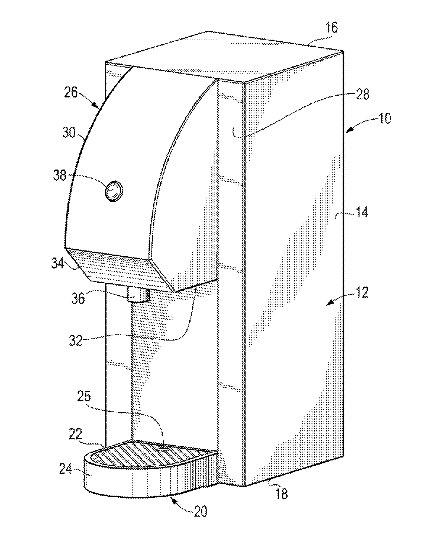
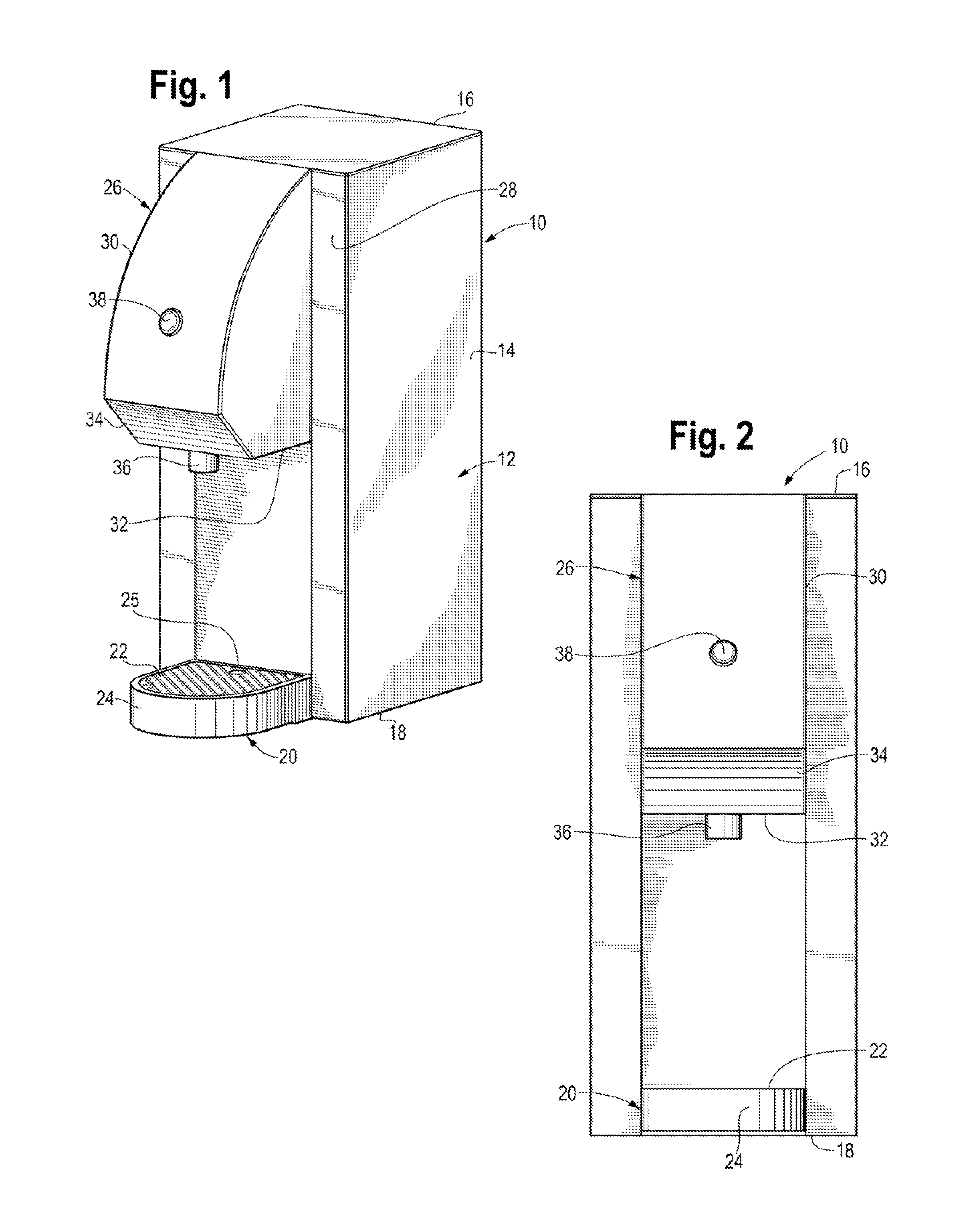
[0041]Referring now to FIGS. 1 and 2, a preferred embodiment of the drink dispenser 10 of the present invention is seen to include a housing 12 with an aft concentrate housing section 14 with a generally rectangular cross section, a top 16 and a bottom 18. Extending forwardly from the front of the bottom 18 is a generally semicircular drip tray 20 with a removable, perforated cup support 22 supported at the top of an upwardly facing drip container body 24. A finger hole 25 in the cup support 22 functions as a handle to facilitate removal of the cup support 22 from the top of drip container body 24 for cleaning.

[0042]Located above the cup support 22 is an overhanging, forward, upper, dispenser housing section 26 cantilever mounted to a central, upper part of the front 28 of the aft housing 14. The forward, upper dispenser housing section 26 has a curved front 30, a flat bottom 32 and a downwardly, inwardly slanted beveled section 34 extending between the front 30 and the bottom 32. E...


PUM


Abstract

An automated mixing drink dispenser (10) establishes a preselected feed rate of concentrate from a concentrate hopper (42) and ratio of concentrate to mixing water fed into a mixing chamber (42) through the Venturi effect created by swirling water fed into a mixing chamber (42) at a preselected water pressure (66) and preselected regulated flow rate (68) associated with the preselected feed rate of the concentrate. Concentrate is fed to a mixing chamber (42) from a concentrate hopper (42) having an open drain hole (50) openly connected to the mixing chamber (42). A stirring mechanism (106, 100, 101, 102, 104) mechanically mixes the concentrate within the concentrate hopper (42) to maintain a uniform density and viscosity and a gas pressure mechanism (92, 94, 96, 86) maintains a uniform head pressure of concentrate to facilitate maintenance of the preselected concentrate flow rate over time. Nitrogen gas in air is pumped through a nitrogen passing filter to fill the space (90) above the concentrate to both maintain head pressure and to reduce deterioration of the concentrate due to interaction with oxygen.

Description

CROSS-REFERENCE TO RELATED APPLICATIONS[0001]This application claims the benefit under 35 U.S.C. 119(e) of U.S. provisional patent application No. 61 / 264,083, filed Nov. 24, 2009.BACKGROUND OF THE INVENTION[0002]1. Field of the Invention[0003]This invention generally relates to an electric, automatic mixing drink dispenser for mixing liquid drink concentrate with water to make a mixed drink on demand and methods of mixing and dispensing drinks with such a mixing drink dispenser[0004]2. Discussion of the Prior Art[0005]Electrical, commercial mixing drink dispensers of type that mix liquid drink concentrate with carbonated or noncarbonated mixing water on demand to make and dispense a mixed drink are well known, but suffer from a number of disadvantages. When a manual switch is actuated, mixing water and drink concentrate from a concentrate hopper are injected into a mixing chamber where they are mixed together to make a mixed beverage and then dispensed. In some cases, actuation of t...

Claims


Application Information

Patent Timeline
Patent Type & Authority Patents(United States)
IPC IPC(8): B67D7/06A47J31/00B67D7/74
CPCB67D1/004A47J31/00B67D2001/1254A47J31/40A47J31/002B67D2001/0481B67D1/1252B67D7/06B67D7/74B67D1/0044B67D1/0885
Inventor LASSOTA, ZBIGNIEW, G.
Owner FOOD EQUIP TECH
Why Eureka
Try Eureka