Micro atomizer

a micro-atomizer and atomizer technology, applied in the direction of combustion types, lighting and heating apparatus, separation processes, etc., can solve the problems of inhalation toxicology studies, reduced vaporization rate, and reduced vaporization rate,

Active Publication Date: 2014-11-11
UNITED STATES OF AMERICA
View PDF37 Cites 1 Cited by
  • Summary
  • Abstract
  • Description
  • Claims
  • Application Information

AI Technical Summary

Benefits of technology

[0014]In view of the foregoing, an exemplary embodiment of a micro atomizer to produce stable aerosol concentrations having MMAD values of less than 10 μm with liquid flow rates in the microliter per minute range is provided. The micro atomizer includes a liquid channel in the shape of a thick-wall tube and a cap having an aerosol outlet orifice whereby a liquid-gas contact space is formed by the internal surface of the cap and

Problems solved by technology

Various methods of generating such aerosols are in use, but suffer from a number of limitations, some of which are described below.
Despite these benefits, the modified, commercially available pneumatic atomizer suffers operational limitations as it is a relatively large piece of equipment requiring liquid flow rates in the milliliter per minute/hour range as well as an air flow rate on the order of 20 liters per minute.
The chambers used in the inhalation toxicology studies that motivated this invention, however, are small in comparison and cannot operate with a generation sy

Method used


Image

  • Micro atomizer
  • Micro atomizer
  • Micro atomizer

Examples


Embodiment Construction

[0023]The embodiments herein and the various features and advantageous details thereof are explained more fully with reference to a non-limiting embodiment that is illustrated in the accompanying drawings and detailed in the following description. Descriptions of well-known components and processing techniques are omitted so as to not unnecessarily obscure the embodiment herein. The examples used herein are intended merely to facilitate an understanding of ways in which the embodiment herein may be practiced and to further enable those of skill in the art to practice the present invention. Accordingly, the examples should not be construed as limiting the scope of the present invention.

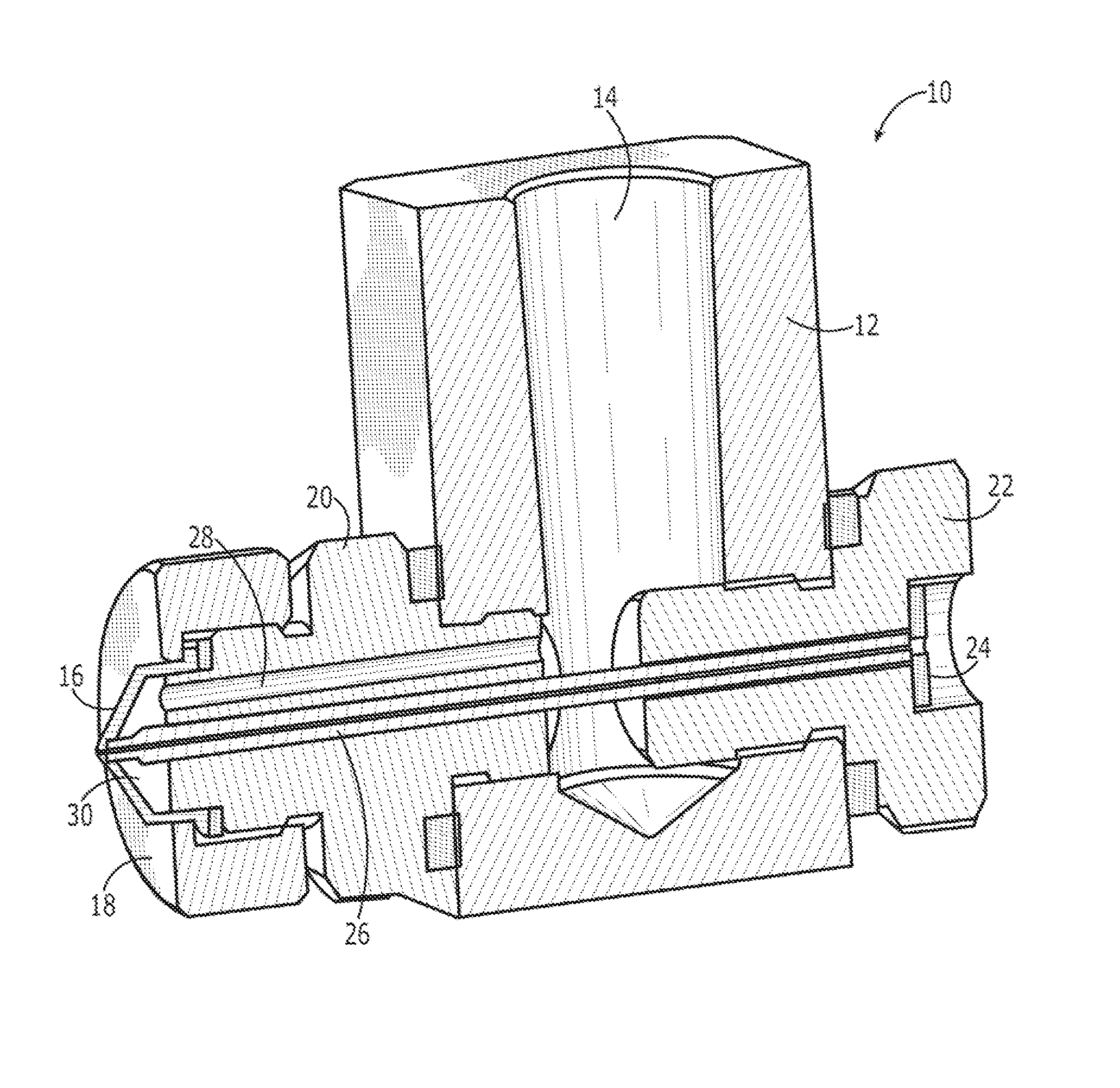
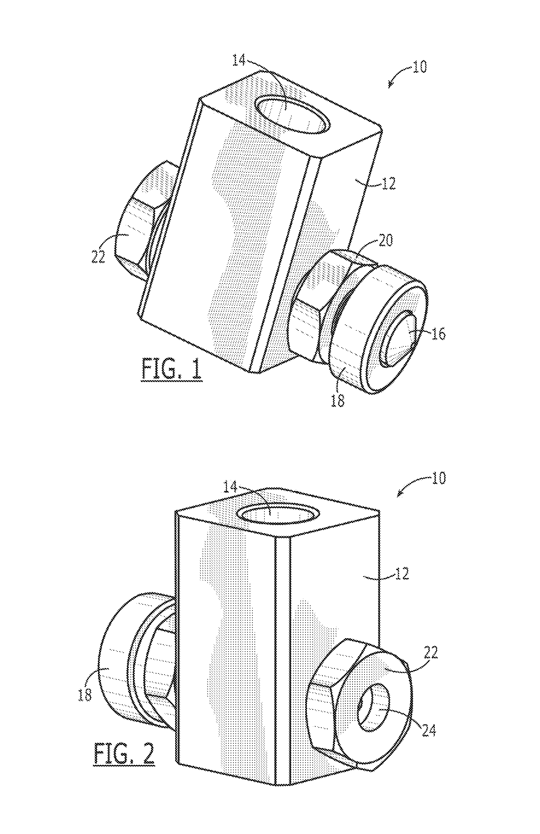
[0024]Turning to FIG. 1, a first perspective view is provided to illustrate the outlet side of a micro atomizer according to an exemplary embodiment of the present invention. Micro atomizer 10 includes body 12 having orifice 14 for connection to a source of pressurized air or an alternative carrier gas...


PUM

PropertyMeasurementUnit
Lengthaaaaaaaaaa
Diameteraaaaaaaaaa
Diameteraaaaaaaaaa

Abstract

A micro atomizer to produce stable aerosol concentrations having an aerosol mass median aerodynamic diameter (MMAD) of less than 10 microns with liquid flow rates in the microliter per minute range is provided. The micro atomizer includes a liquid channel in the shape of a thick-wall tube and a cap having an aerosol outlet orifice whereby a liquid-gas contact space is formed by the internal surface of the cap and the substantially flat end of the liquid channel. Pressurized carrier gas and the liquid to be aerosolized are allowed to come into contact within a precisely formed liquid-gas contact space. The desired aerosol characteristics are accurately established, stable, and reproducible. In an exemplary embodiment, the micro atomizer is used with a syringe and syringe drive to provide a continuous liquid source for aerosol generation.

Description

GOVERNMENT INTEREST[0001]The invention described herein may be manufactured, used, and / or licensed by or for the United States Government.BACKGROUND[0002]1. Technical Field[0003]The present invention generally relates to the technical field of gas and liquid contact devices and methods to produce an aerosol, and, more particularly, to an atomizer for use in aerosol generation at continuous, but ultra-low liquid flow rates such as 50 microliters per hour. Accordingly, the device of the present invention is referred to herein as a micro atomizer.[0004]2. Description of the Related Art[0005]Research in inhalation toxicology requires the ability to generate stable aerosol concentrations of a respirable particle size in a consistent manner from day to day and experiment to experiment. Respirable, as used herein, refers to airborne particles capable of entering and depositing in the upper airways and the lower airways of the lungs. The upper airways include the trachea and the primary, se...

Claims


Application Information

Patent Timeline
IPC IPC(8): B05B7/00
CPCB05B7/0075B05B7/0012B05B7/066A61M11/00A61M15/025A61M11/06A61M15/00
Inventor HORSMON, MICHAEL S.CROUSE, CHARLES L.KREIS, RICHARD J.
Owner UNITED STATES OF AMERICA
Why Eureka
Try Eureka