Apparatus and methods for percutaneous cochlear implantation

Inactive Publication Date: 2014-11-11
VANDERBILT UNIV
View PDF6 Cites 17 Cited by
  • Summary
  • Abstract
  • Description
  • Claims
  • Application Information

AI Technical Summary

Benefits of technology

The present invention relates to a method and apparatus for percutaneous cochlear implantation (PCI). The method includes steps of implanting anchor members in the skull of a patient, attaching a docking frame to the anchor members, and configuring a parallel robot based on a computed tomography (CT) image. The parallel robot has a top platform and a base platform connected via linear actuators. The apparatus includes a docking frame with a central through hole for accessing the brain and three or more fiducial members protruding from it. The technical effects of this invention include improved accuracy of PCI and reduced risk of complications during surgery.

Problems solved by technology

Microsterotactic frames (i.e. bone-attached rigid fixtures custom-made for each patient) are capable of high accuracy, but require manufacturing delays.

Method used


Image

  • Apparatus and methods for percutaneous cochlear implantation
  • Apparatus and methods for percutaneous cochlear implantation
  • Apparatus and methods for percutaneous cochlear implantation

Examples


example 1

[0078]FIG. 4 shows an AIM frame attached to a human skull according to one embodiment of the present invention. The AIM frame has a rigid pre-positioning frame, also referred herein as a docking frame, that is mounted to the skull with surgical screws, a robot that attaches to titanium spheres on the pre-positioning frame, and an electronic equipment enclosure. The robot has a top platform and a bottom platform. Both the base platform of the robot and the pre-positioning frame have large holes through their centers to allow the surgical tools (drill and cochlear implant insertion tool) to pass through to the target.

[0079]Both the top platform and base platform of the AIM frame are milled from polyetherimide, an autoclavable thermoplastic that maintains high rigidity and tensile strength at high temperatures. The joints and all fasteners are made of autoclavable metals. The pre-positioning frame is made from an autoclavable polyetherimide or acrylonitrile butadiene styrene (ABS). It ...

example 2

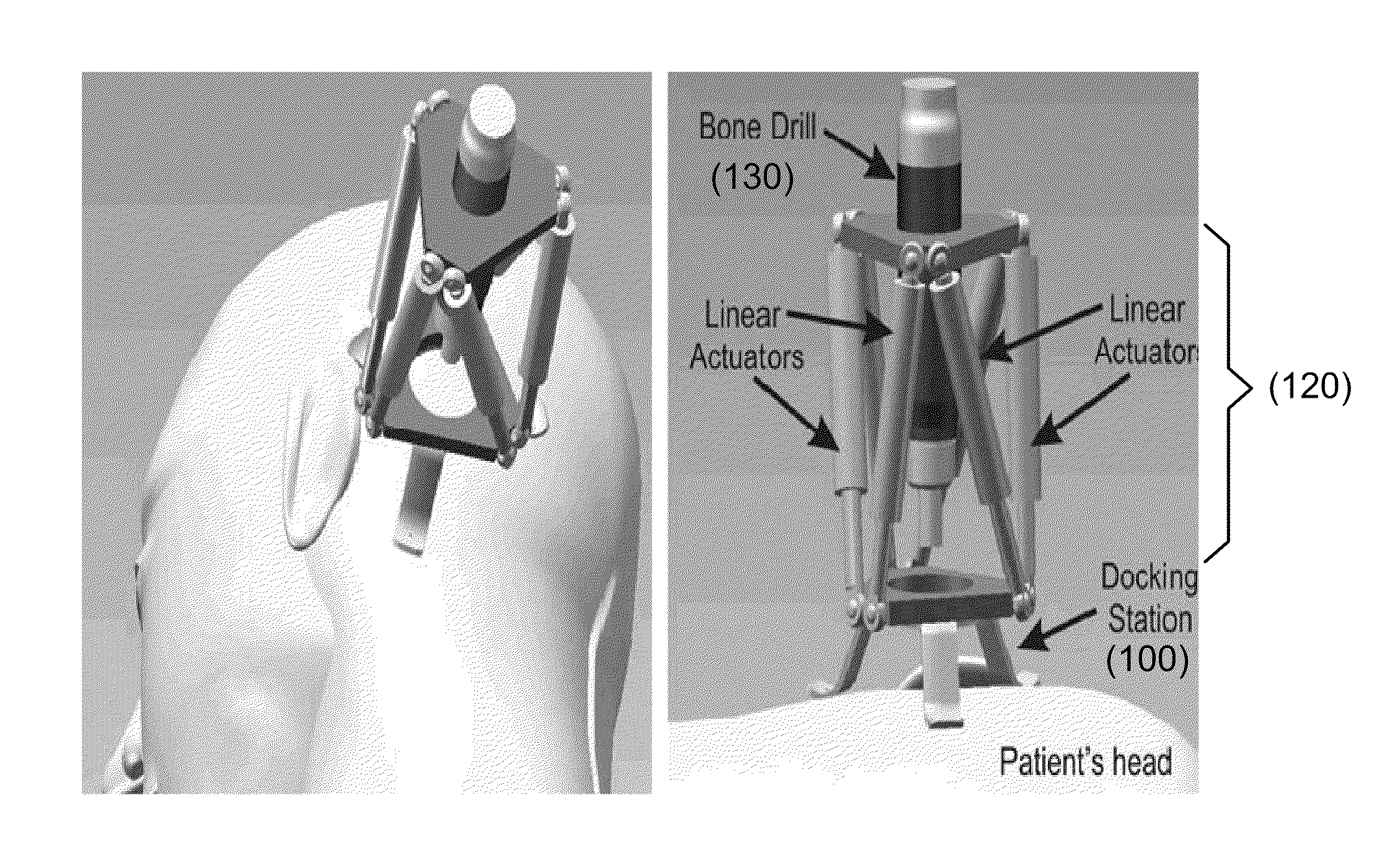
[0091]FIG. 10 shows schematically (a) a mechatronic microtable attached to a human skull, and (b) a close-up view of the mechatronic microtable, according to another embodiment of the present invention. The mechatronic microtable comprises a docking frame 100 and a parallel robot 120 mounted on the docking frame 100. The top plate of the parallel robot 120 receives a surgical tool 130 such as a bone drill. Design objectives for the parallel robot are summarized in Table 1.

[0092]FIG. 11 shows schematically in part the docking frame 100. Fiducial anchors 102 pass through holes in the docking frame 100 through incisions in the skin 108 and then self-tap into the bone 110. A retaining clip 106 is then slid into one of several grooves in the lower part of each of the fiducial anchors 102, and a nut 104 is tightened. The retaining clip 106 avoids using the pliable skin as platform for the docking frame 100. The top portion of the fiducial anchor 102 is a hexagonal part that serves both to...


PUM


Abstract

A method and apparatus of percutaneous cochlear implantation (PCI). In one embodiment, the method includes the steps of (a) implanting a plurality of anchor members in a skull of a patient surrounding an ear of the patient, (b) attaching a docking frame to the plurality of anchor members, wherein the docking frame has a docking platform and a plurality of fiducial members, (c) acquiring a computed-tomography (CT) image of an area of the patient's head including the ear and the plurality of fiducial members, (d) determining a centroid of each of the plurality of fiducial members and a trajectory for a PCI according to the CT image, (e) configuring a parallel robot by a computer processor according to the CT image such that a top platform of the parallel robot is aligned with the trajectory with respect to the centroids of the plurality of fiducial members, (f) attaching the configured parallel robot to the docking frame, and (g) performing the PCI using one or more surgical tools received by the top platform of the parallel robot.

Description

CROSS-REFERENCE TO RELATED PATENT APPLICATION[0001]This application claims the benefit, pursuant to 35 U.S.C. §119(e), of U.S. provisional patent application Ser. No. 61 / 358,579, filed on Jun. 25, 2010, entitled “A BONE-ATTACHED PARALLEL ROBOT FOR PERCUTANEOUS COCHLEAR IMPLANTATION, MECHATRONIC MICROTABLE AND APPLICATIONS OF SAME,” by Robert F. Labadie et al., which is incorporated herein by reference in its entirety.[0002]Some references, which may include patents, patent applications and various publications, are cited in a reference list and discussed in the description of this invention. The citation and / or discussion of such references is provided merely to clarify the description of the present invention and is not an admission that any such reference is “prior art” to the invention described herein. All references listed, cited and / or discussed in this specification are incorporated herein by reference in their entireties and to the same extent as if each reference was indivi...

Claims


Application Information

Patent Timeline
IPC IPC(8): A61N1/05A61B19/00A61B17/34
CPCA61B2019/2226A61B17/3403A61B2017/3407A61N1/0541A61B17/3468A61B19/201A61B19/2203A61B34/30A61B90/11A61B2034/304
Inventor LABADIE, ROBERT F.FITZPATRICK, J. MICHAELMITCHELL, JASON E.BLACHON, GREGOIRE S.TOENNIES, JENNAWEBSTER, III, ROBERT J.WITHROW, THOMAS J.
Owner VANDERBILT UNIV
Why Eureka
Try Eureka