Device of a pair of claw-type rotors having same profiles

a technology of claw-type rotors and rotors, which is applied in the direction of gearing, hydraulic equipment, liquid fuel engines, etc., can solve the problems of inability to fully define the rotor and the conjugate rotor, noise and vibration, and noise and vibration of the conventional claw-type rotor, so as to prolong the life of the device, avoid noise and vibration, and mitigate mechanical fatigue

Active Publication Date: 2014-11-18
LIUNG FENG INDAL
View PDF13 Cites 0 Cited by
  • Summary
  • Abstract
  • Description
  • Claims
  • Application Information

AI Technical Summary

Benefits of technology

[0006]Accordingly, an object of the present invention is to provide a device of a pair of claw-type rotors having same profiles, the device comprises a defined rotor and a conjugate rotor intermeshing with and conjugating to each other. Both the defined and conjugate rotors have same even number of claws of same profiles by setting parameters, and rotate in a continuously and smoothly motion curve, so as to avoid noise and vibration during the compressing motion in periodic cycles and to mitigate mechanical fatigue resulting from intermeshing of the defined and conjugate rotors, whereby extending the lifespan of the device of the claw-type rotors.

Problems solved by technology

However, conventional claw-type rotors have drawbacks that noise and vibration occur during the process of intermeshing and engaging of the rotors.
It is because sharp-portion curves of two claws are not smoothly and continuously formed, whereby causing the defined rotor and the conjugate rotor to intermesh incompletely.
Noise and vibration then arise during the process of compressing motion, and even worse such incompletely intermeshing may wear out the rotors and shorten the lifespan thereof.

Method used


Image

  • Device of a pair of claw-type rotors having same profiles
  • Device of a pair of claw-type rotors having same profiles
  • Device of a pair of claw-type rotors having same profiles

Examples


first embodiment

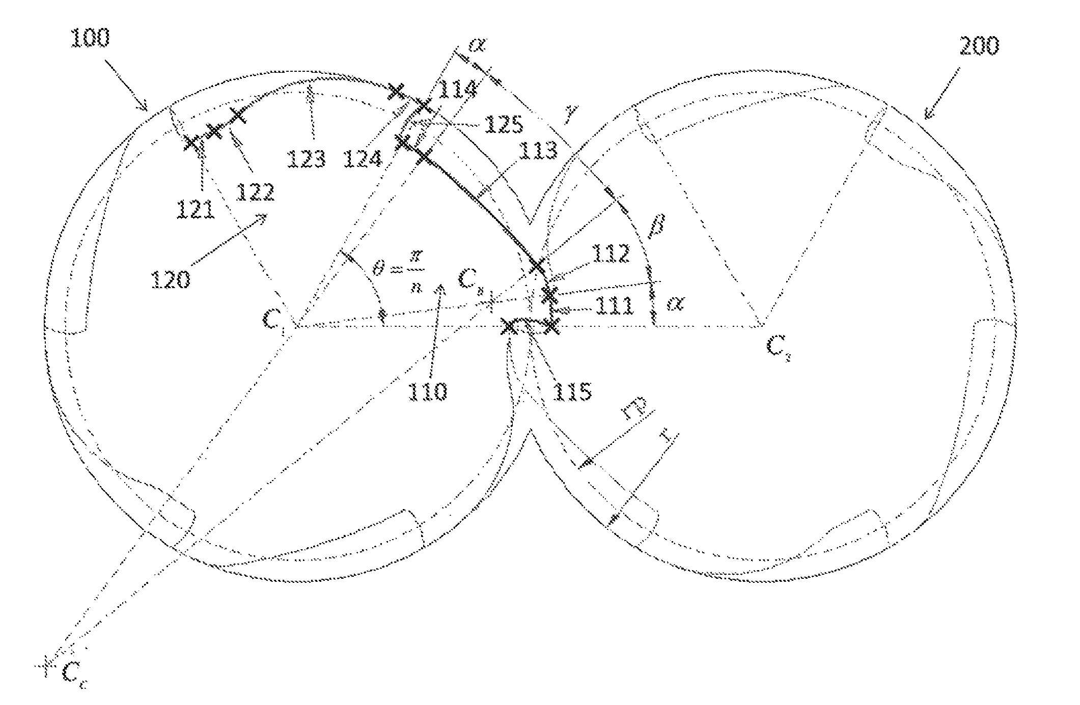
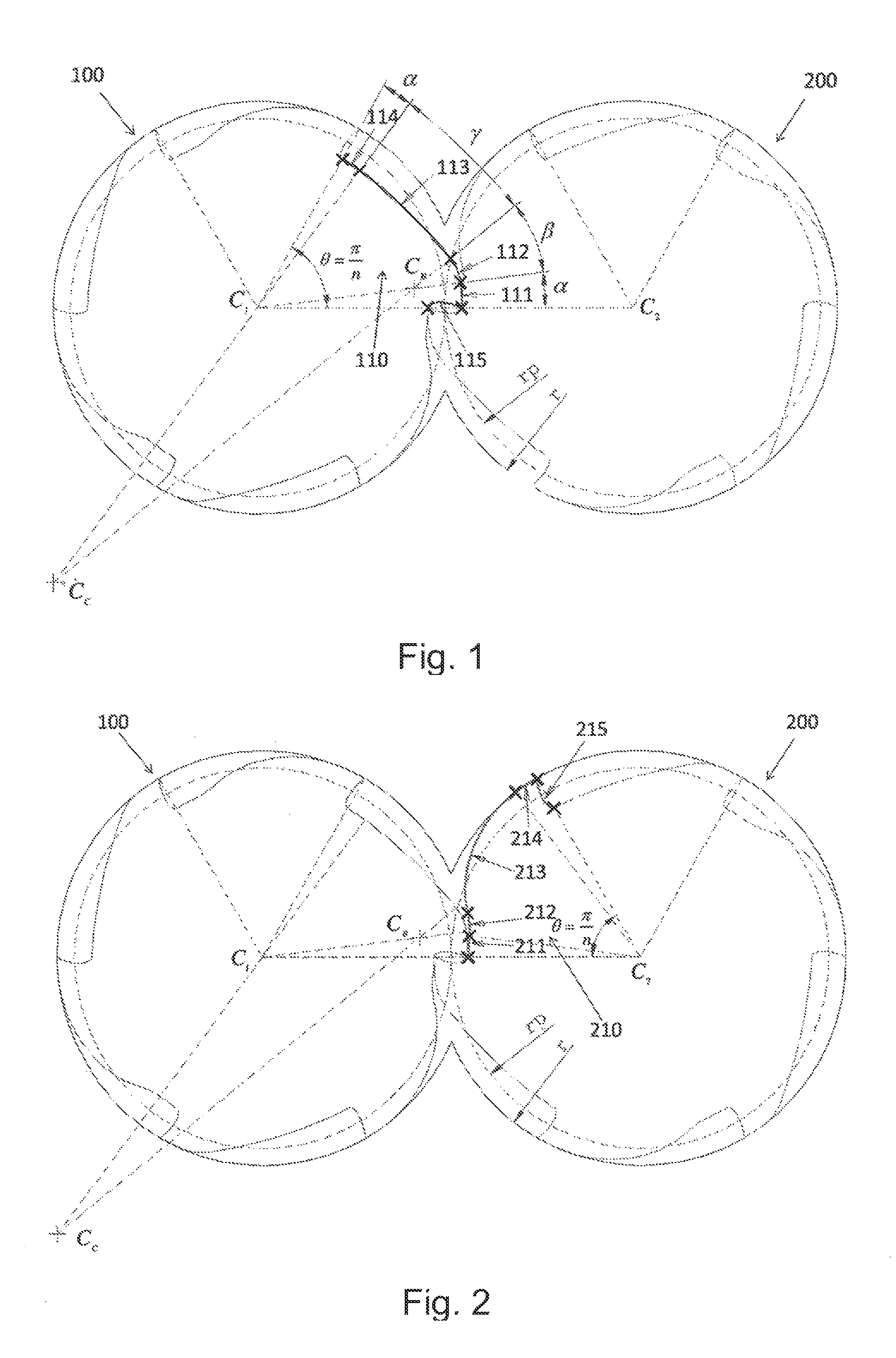
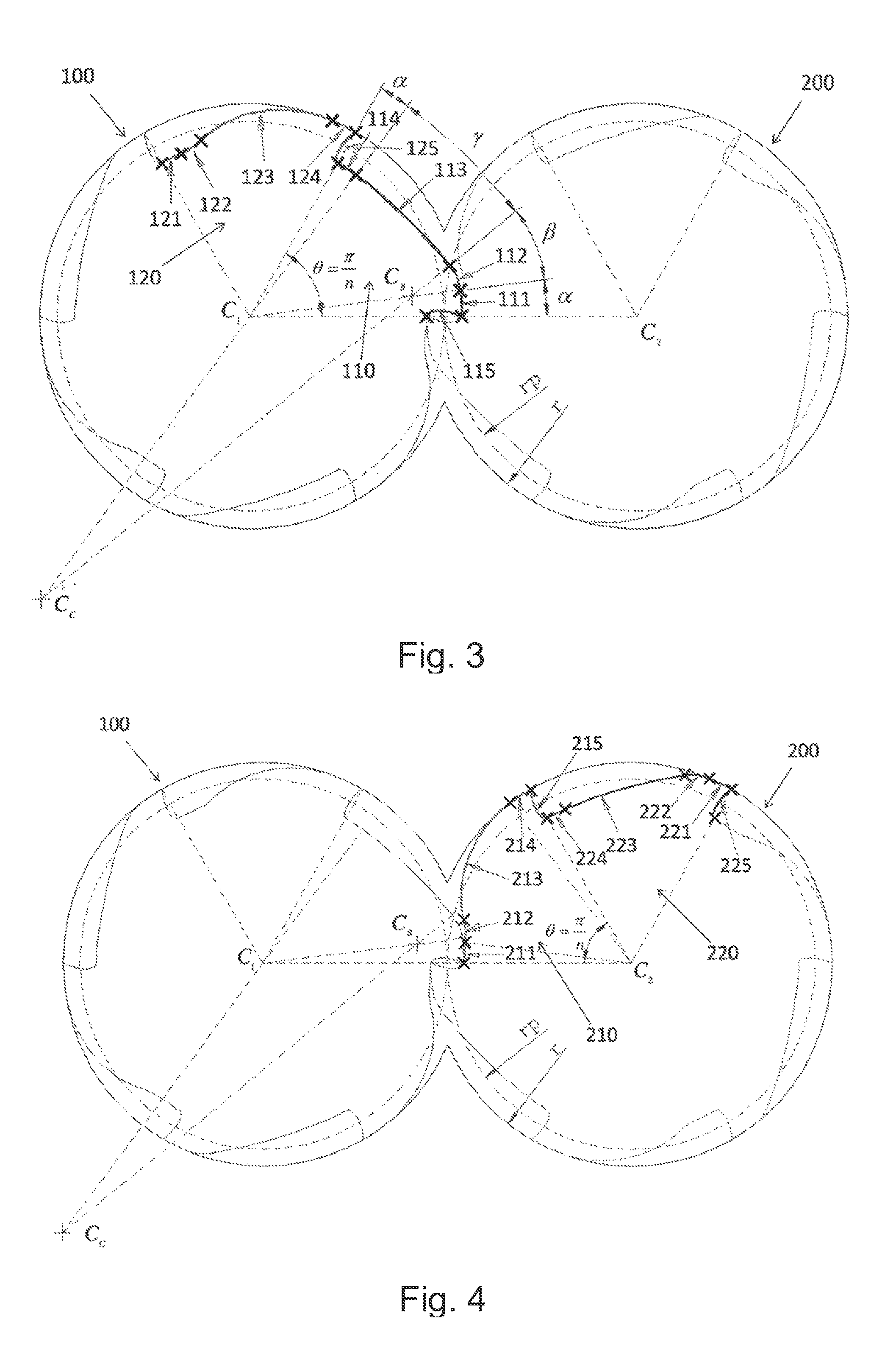
[0015]Referring to FIGS. 1 to 4 showing a device of a pair of claw-type rotors of the present invention, the pair of claw-type rotors have same profiles and comprise a defined rotor 100 and a conjugate rotor 200 both intermeshing with and conjugating to each other. Referring to FIG. 1, in this embodiment the defined rotor 100 and the conjugate rotor 200 each has six claws, and profiles of the claws of the defined and conjugate rotors 100 and 200 are same as each other. A first claw of the defined rotor 100 has a cross-section profile including a sharp portion and a root portion that are defined by predetermined non-linear equations. A cross-section profile of a first claw 210 of the conjugate rotor 200 is defined by the conjugate theory (as shown in FIG. 2). The first claw 210 of the conjugate rotor 200 is imaged to the defined rotor 100 to form a second claw of the defined rotor 100, while the cross-section profile of the first claw 110 of the defined rotor 100 is imaged to the con...

second embodiment

[0024]In the second embodiment the second and third arcs 112 and 113 jointly form an angle of 360° divided by the number of claws with respect to a center C1 of the defined rotor 100. The epicycloid 115 is defined by a start point and an end point, the start point spaced away from the center C1 of the defined rotor 100 at a distance which is the rotor radius r subtracted from two times the pitch circle radius rp, while the end point is spaced apart from the center C1 of the defined rotor 100 with the rotor radius r, and the start point and end point of the epicycloid 115 are in alignment with the center C1. The second arc 112 starts from the end point of the epicycloid 115 and has a center CB located at a point between and in alignment with both the centers C1 and C2 of the defined rotor 100 and conjugate rotor 200. The third arc 113 ends at a distance of the rotor radius r subtracted from two times the pitch circle radius rp and is located at a point where an angle of the defined r...


PUM


Abstract

The present invention is to provide a device of a pair of claw-type rotors having same profiles, the device includes a defined rotor and a conjugate rotor intermeshing with and conjugating to each other. The defined rotor includes a first claw having a cross-section profile having an epicycloid, a first arc, a second arc, a third arc, and a fourth arc all connected together in sequence in a counterclockwise direction. The first, second, third, and fourth arcs are connected with slope continuity, whereby locations of centers, values of radiuses and arc angles of the second and third arcs are capable of being defined in accordance with the slope continuity and geometric relations between the first and fourth arcs. The conjugate rotor has a first claw having a cross-section profile generated by utilizing a conjugate curve corresponding to the first claw of the defined rotor.

Description

BACKGROUND OF THE INVENTION[0001]1. Field of the Invention[0002]The present invention relates to a claw-type rotor device, and more particular to a device of a pair of claw-type rotors having same profiles that enables a smooth process of intermeshing of the rotors without producing noise and mechanical fatigue, and provides an even number of claws for each rotor by setting suitable parameters.[0003]2. Related Art[0004]Conventional claw-type rotors are varied in structure according to practical applications. Each of rotors operating in pairs may have either an odd number of claws or an even number of claws. Whatever types of claw-type rotors are, conventional claw-type rotors operating in pairs generally have a conjugate rotor and a defined rotor both intermeshing and engaging with each other with claws thereof for providing compressing motion in periodic cycles. Relevant claw-type rotors are disclosed in U.S. Pat. Nos. 1,426,820, 5,149,256, 4,406,601, 4,324,538, 4,224,016, 4,430,05...

Claims


Application Information

Patent Timeline
Patent Type & Authority Patents(United States)
IPC IPC(8): F01C1/12F16H55/08F01C1/18F01C1/08F16H55/17
CPCF01C1/123F16H55/08F01C1/084Y10T74/19642Y10T74/1987F01C1/08F01C1/20F04C2/10F04C18/18F04C18/20F16H1/32F16H55/17
Inventor HSU, TSANG LINCHUNG, TIEN-TUNG
Owner LIUNG FENG INDAL
Why Eureka
Try Eureka