Self leveling dry dock lift

a dry dock and self-leveling technology, applied in dry docking, special-purpose vessels, waterborne vessels, etc., can solve the problems of preventing system operation smoothly, affecting the reliability of automatic systems, and laborious and difficult-to-use systems, etc., and achieves the effect of simple manufacture, installation and us

Inactive Publication Date: 2014-11-18
ROGERSON L KEITH
View PDF7 Cites 0 Cited by
  • Summary
  • Abstract
  • Description
  • Claims
  • Application Information

AI Technical Summary

Benefits of technology

[0003]The present disclosure is directed broadly to dry dock systems that automatically raise and level watercraft. In general, raising and leveling a boat is accomplished by a submerged arrangement, which is in communication with dry dock tanks. The arrangement may be positioned or mounted below the dry dock tanks in such a way as to emulate the orientation of the dry dock tanks to direct air to fill appropriate tanks in order to level and raise the dry dock. The components of the disclosed embodiments and their equivalents are simple to manufacture, install and use.
[0007]The means for guiding may be an enclosure and may further include a shield connected to the enclosure. The shield may have an aperture to permit water entry but is sized to prevent growth of marine life. This aspect of the disclosure may also include a depth setting device located in at least one of the flotation chambers. Water will hydraulically lock (“hydro-lock”) the depth setting device to halt transfer of air out of tanks and to limit sinking of the flotation chambers.

Problems solved by technology

These systems are labor intensive and difficult to use.
For instance, mechanical friction in the valves can prevent the systems from functioning smoothly.
On the other hand, automatic systems are relatively expensive and are often unreliable.

Method used


Image

  • Self leveling dry dock lift
  • Self leveling dry dock lift
  • Self leveling dry dock lift

Examples


Embodiment Construction

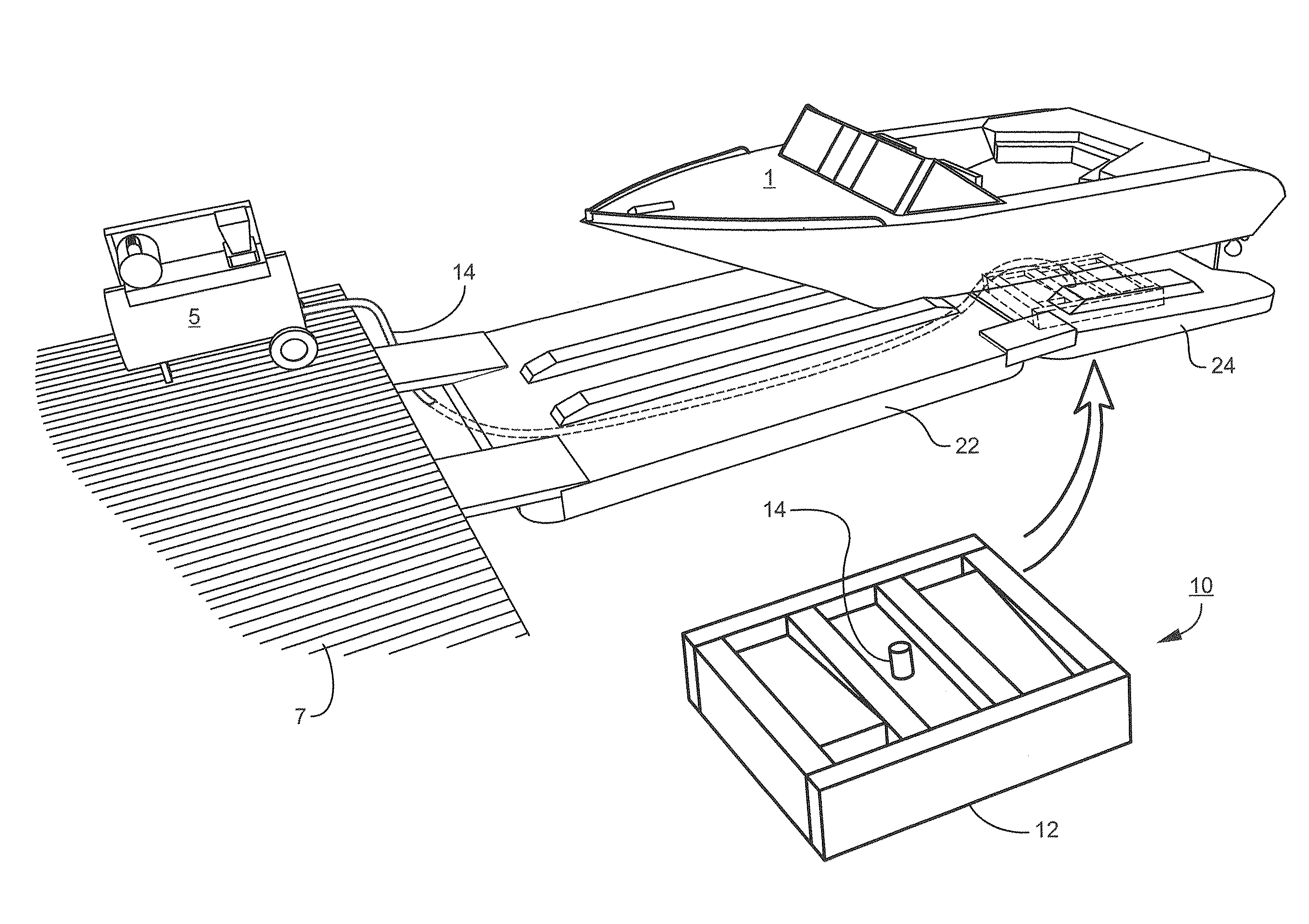
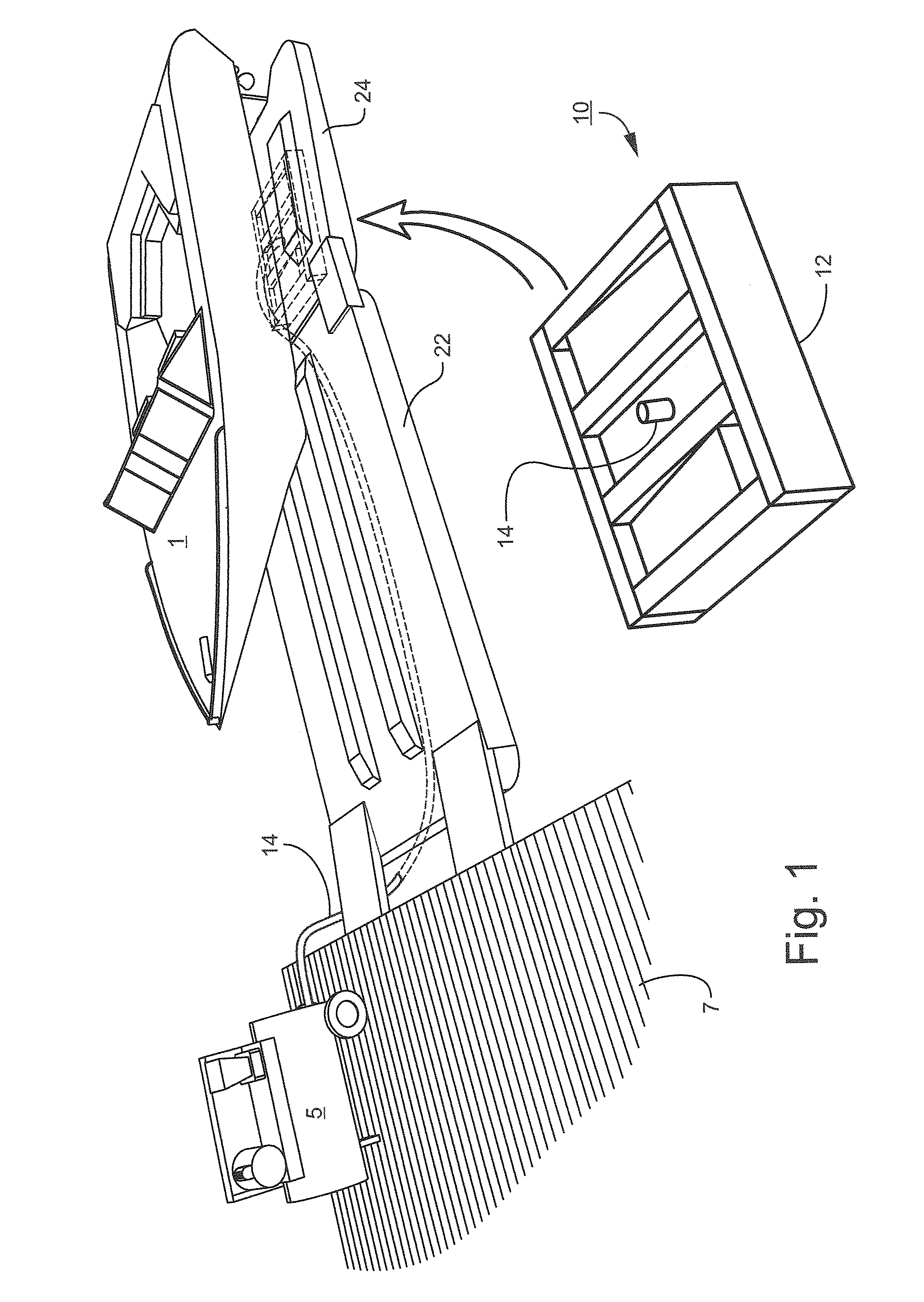
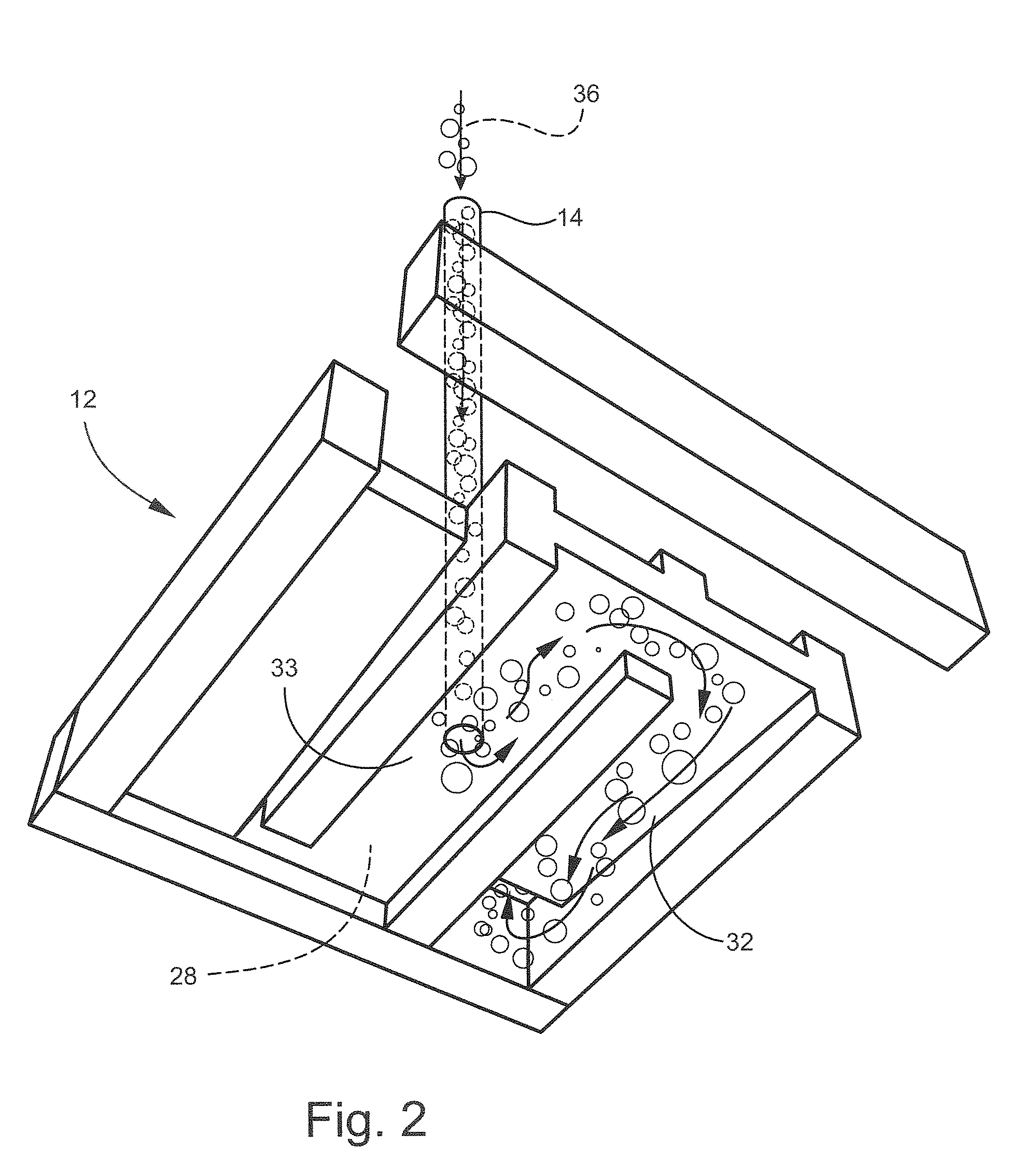
[0020]Detailed reference will now be made to the drawings in which examples embodying the present subject matter are shown. The detailed description uses numerical and letter designations to refer to features of the drawings. Like or similar designations of the drawings and description have been used to refer to like or similar parts of various exemplary embodiments.

[0021]The drawings and detailed description provide a full and written description of the present subject matter, and of the manner and process of making and using various exemplary embodiments, so as to enable one skilled in the pertinent art to make and use them, as well as the best mode of carrying out the exemplary embodiments. However, the examples set forth in the drawings and in the detailed description are provided by way of explanation only and are not meant as limitations of the disclosure. The present subject matter thus includes any modifications and variations of the following examples as come within the sco...


PUM


Abstract

An air direction device is submerged under a dry dock. The device imitates the orientation of the dry dock and is in communication with an air source, which pipes air under the device. The air travels to the most elevated portion of the device, which in turn directs the air into a depressed tank to correct dry dock imbalance.

Description

BACKGROUND OF THE DISCLOSURE[0001]Many conventional dry docks use air-supplied systems operated by an assortment of valves and switches. These systems are labor intensive and difficult to use. For instance, mechanical friction in the valves can prevent the systems from functioning smoothly. On the other hand, automatic systems are relatively expensive and are often unreliable. Many boat owners and dry dock operators, therefore, choose to use winches and other manual devices to raise vessels out of water.[0002]What is needed in the industry is a dry dock system that is cost effective, easy to manufacture, and simple to use.BRIEF SUMMARY OF THE DISCLOSURE[0003]The present disclosure is directed broadly to dry dock systems that automatically raise and level watercraft. In general, raising and leveling a boat is accomplished by a submerged arrangement, which is in communication with dry dock tanks. The arrangement may be positioned or mounted below the dry dock tanks in such a way as to...

Claims


Application Information

Patent Timeline
Patent Type & Authority Patents(United States)
IPC IPC(8): B63C1/02
CPCB63C1/06B63C1/10
Inventor ROGERSON, L., KEITH
Owner ROGERSON L KEITH
Why Eureka
Try Eureka