Linear motion guide unit

a technology of motion guide unit and guide rod, which is applied in the direction of linear bearings, shafts and bearings, bearings, etc., can solve the problems of poor mechanical strength of overall linear motion guide units, excessively large volume of porous compacts, and inability to make porous compacts large in volume, etc., to achieve the effect of increasing the reserved amount of lubricant, enhancing the volume of the second reservoir, and increasing the thickness or volum

Active Publication Date: 2014-11-18
NIPPON THOMPSON
View PDF8 Cites 0 Cited by
  • Summary
  • Abstract
  • Description
  • Claims
  • Application Information

AI Technical Summary

Benefits of technology

[0010]The present invention has for its primary object to overcome the major challenges as stated earlier, and to provide a linear motion guide unit adapted to be used in a reciprocating mechanism built in semiconductor fabricating equipment, machine tools, industrial robots, and so on. The linear motion guide unit has a binding strip to fasten a retainer plate to keep the rollers against falling away from a slider. The present invention is particularly envisaged coping with lack of space for a lubrication system chiefly because grooves to fit over the binding strip are cut into an outward end surface of an end cap, which is in the face of the associated end seal. To this end, the present invention provides a linear motion guide unit in which an end cap has a concavity on an outward end surface thereof which faces directly towards an end seal of the slider, and a open-cellular or porous compact impregnated with lubricant fits into the concavity, the end cap having a hole to communicate the concavity with a turnaround passage inside the end cap no as to carry out application of the lubricant around rolling elements while rollers roll across the turnaround passage. With the linear motion guide unit constructed according to the present invention, more especially, application of lubricant to the turnaround passage can be done on the side of an end seal by using an injection needle of a syringe-type applicator and resupply of lubricant can be done at the same time. Thus, the lubrication system itself may be simplified in construction. Moreover, the porous compact, as adapted to conform to the deep concavity in the end cap, is allowed to have a lubricant reservoir capable of retaining lubricant therein as large in volume as possible. Even if the end cap is small in construction, the porous compact itself can have the lubricant reservoir which is impregnated with ample lubricant enough to conduct steady and sustainable application of lubricant around the rollers and further the resupply of lubricant can be carried out easily with accompanying maintenance-free lubrication over a long-lasting period.
[0018]With the linear motion guide unit constructed as stated earlier, the second reservoir of the porous compact lying in the middle of the end cap is made larger in thickness or volume than in the conventional construction to increase the reserved amount of lubricant. In addition, the boss portion lying in the middle of the end cap is reduced in size to make it possible to out partially the first lubricating hole in the boss portion to provide the slit. Thus, the present invention makes it easier to enhance the volume of the second reservoir of the porous compact to increase the amount of lubricant preserved in the second reservoir. Since the lubricating hole in the end cap is cut partially in the sliding direction of the slider to make the slit where the porous compact is exposed to the lubricating hole, the lubricant flowing in the lubricating hole is absorbed in part in porous compact. As a result, the lubricant is applied to the turnaround passages through the lubricating grooves, while simultaneously the lubricant in part is resupplied directly to porous compact with accompanying maintenance-free lubrication over a long-lasting period.
[0019]The linear motion guide unit of the present invention is concerned with a miniature roller-type linear motion guide unit in which application of lubricant around the rolling elements is carried out in the turnaround passages. The use of the lubricating hole in place of the conventional grease nipple results in ensuring a plenty space for the porous compact in the end cap thereby to allow the porous compact to have the volume large for the liner motion guide unit. In addition to the resupply of lubricant from the lubricating hole through the lubricating grooves, the direct resupply of lubricant into the porous compact is made possible by exposure of the porous compact to the lubricating hole. Even though the linear motion guide unit is very small in construction, thus, the lubrication system designed according to the present invention makes it possible to carry out the direct resupply of lubricant into the porous compact and, therefore, succeeds in retaining constantly a plenty of lubricant with accompanying maintenance-free lubrication over a long-lasting period. With the linear motion guide unit of the present invention, moreover, the reservoir of the porous compact can be placed below the lubricating hole because there in no need of grease nipple. As a result, the volume of the porous compact in the present invention increases by about 20% than in the prior liner motion guide unit with grease nipple to make it possible to retain more amount of lubricant in the porous compact. Thus, the porous compact retainable more amount of lubricant helps steady and positive application of the lubricant around the rolling elements with maintenance-free operation for lubrication over a prolonged service life. With the linear motion guide unit constructed as stated earlier, it is allowed to connect the porous compacts in substantially U-shape. This connection of the porous compacts makes mobility of lubricant in the porous compacts easier to protect the lubricant retained in any only one of the porous compacts would be consumed lack of balance.

Problems solved by technology

Because the grooves to retain the binding strip take up a large space across the outward end surface of the end cap and further there is no space for the provision of the grease nipple in the end cap, it is impractical to make the porous compact large in volume at either side of the lubricant reservoir and the applicator nose coming into contact with the rolling elements.
It was found that making the porous compact excessively large in volume would render overall the linear motion guide unit worse or less in mechanical strength.

Method used


Image

  • Linear motion guide unit
  • Linear motion guide unit
  • Linear motion guide unit

Examples


Embodiment Construction

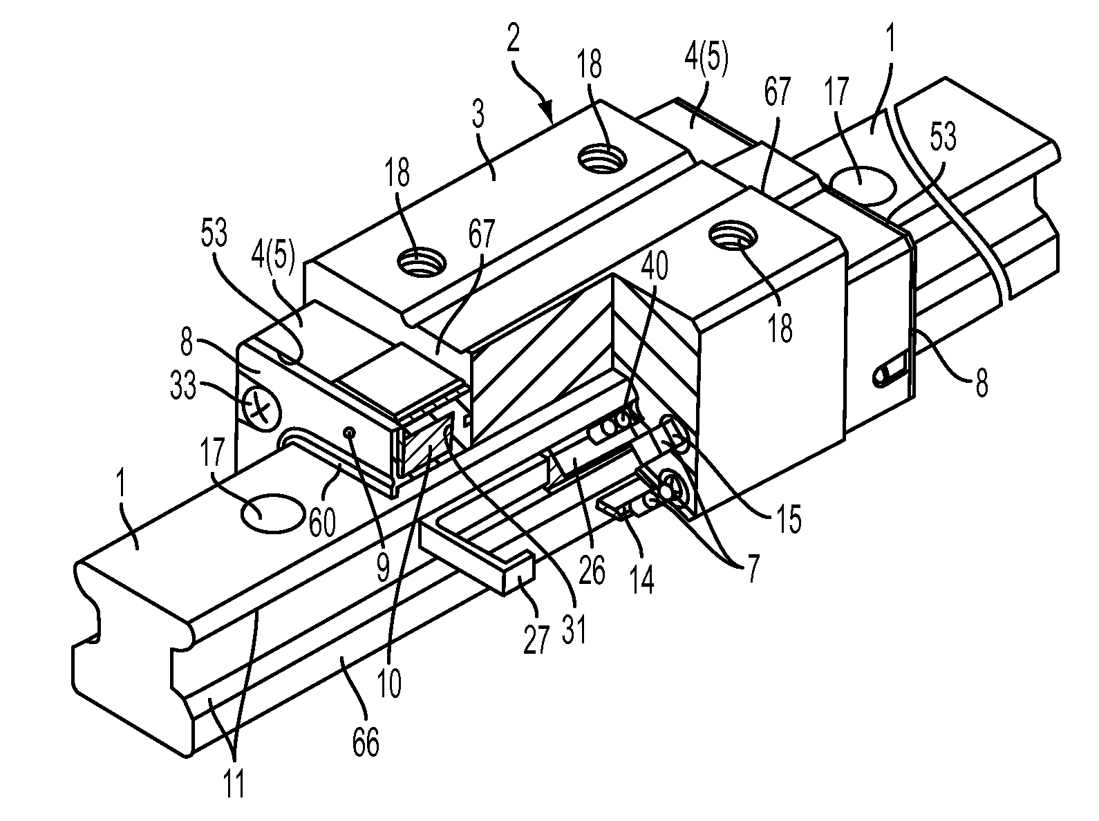
[0045]The linear motion guide unit of the present invention is adapted for use in any relatively sliding components in machinery as diverse as robotic machines, semiconductor fabricating equipment, precision machines, measurement / inspection instruments, medical instruments, micromachines, and so on. Especially, the present invention is intended to develop the linear motion guide unit, which can cope with demand to keep better lubrication to the rolling elements, thereby making sure of smooth movement of the rolling elements throughout the circulating circuit.

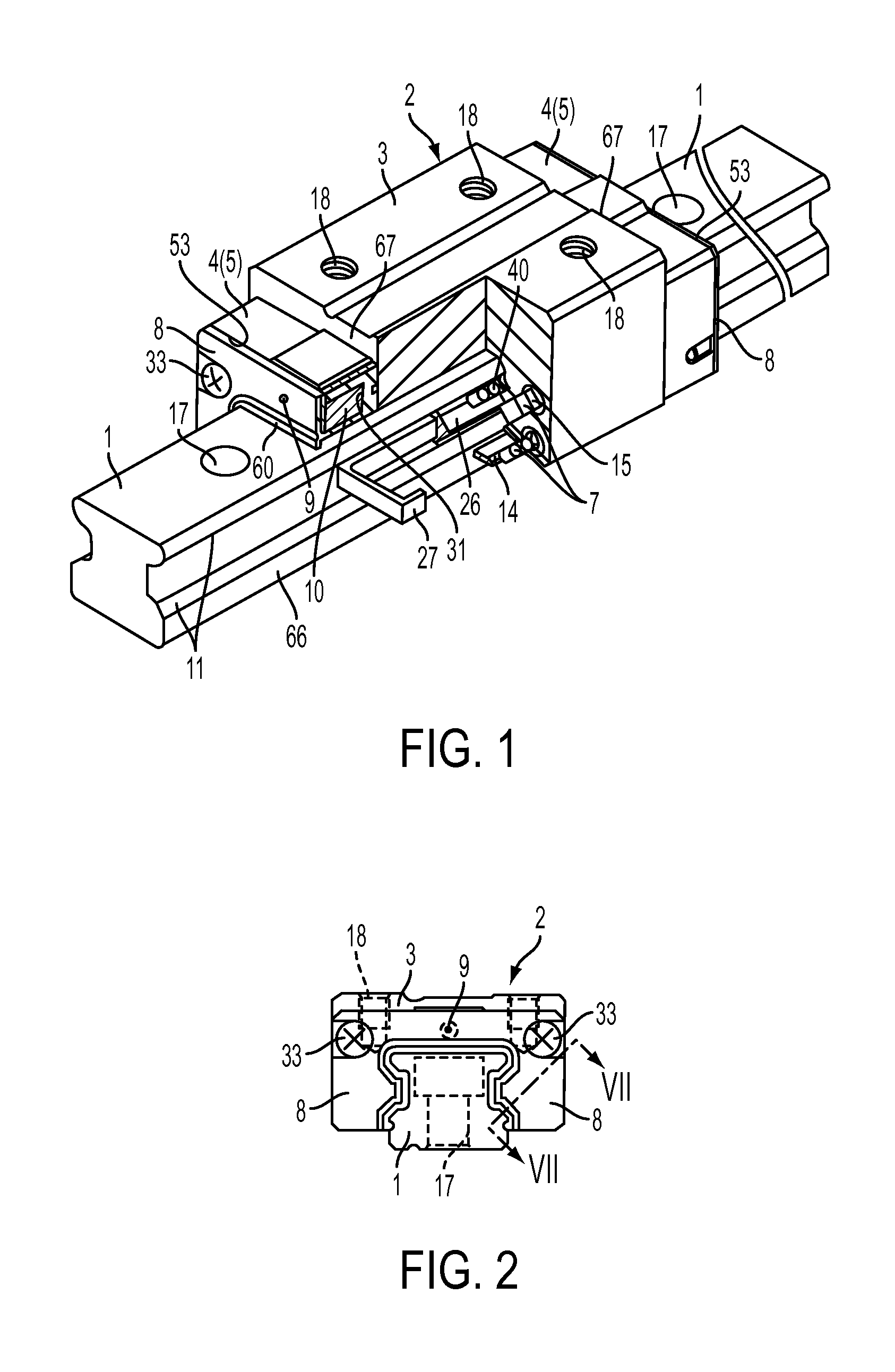
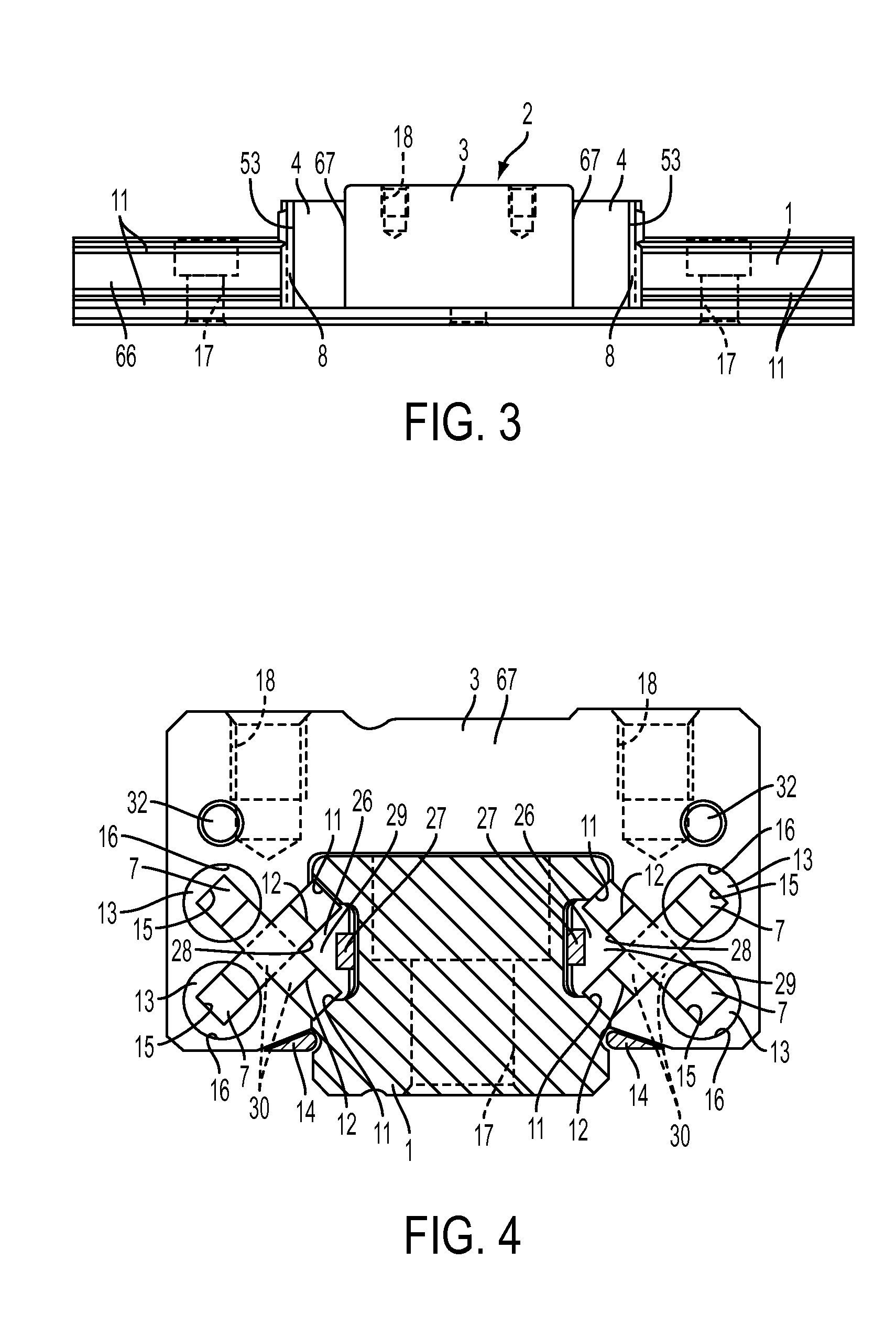
[0046]A preferred embodiment of the linear motion guide unit constructed according to the present invention will be described in detail by reference to the drawings. The linear motion guide unit of the present invention is of the sort having four rows of load-carrying races for the rollers and in general composed of an elongated guide rail 1 having only a pair of first raceway surfaces 11 lying one on top of the other and extend...


PUM


Abstract

Lubrication for rolling elements is carried out within the turnaround passages. For resupply of lubricant, the end seals and end caps have lubricating holes lying in alignment with each other to allow any lubricant injection needle piercing through there. A porous compact impregnated with lubricant fits in a concavity in the end cap. The concavity has an opening to communicate the concavity with the turnaround passage. The porous compact is composed of reservoirs, conjunctive parts, and applicator noses extending through openings to expose their tips into the turnaround passages. The lubricating hole in the end cap has a slit through which the porous compact is exposed to the lubricating hole to allow the lubricant flowing into the porous compact.

Description

FIELD OF THE INVENTION[0001]The present invention relates to a linear motion guide unit comprised of an elongated guide rail and a slider designed to move on the elongated guide rail relatively to the guide rail by virtue of more than one rolling element, and in which the slider has therein a porous compact for lubrication.BACKGROUND OF THE INVENTION[0002]Linear motion guide units have been extensively applied in recent years between relatively sliding parts for linear reciprocating mechanism used in increased industrial fields including semiconductor fabricating equipment, machine tools, industrial robots, and so on. Most prior linear motion guide units have been ordinarily fed with lubricant at regular intervals through any oiling port to ensure smooth lubrication for the rolling elements throughout a circulating circuit. Recently advanced machines and instruments, nevertheless, are increasingly needed to make them virtually maintenance-free from many aspects of conserving energy ...

Claims


Application Information

Patent Timeline
Patent Type & Authority Patents(United States)
IPC IPC(8): F16C33/66F16C29/06F16C33/10
CPCF16C33/6681F16C33/6648F16C29/065F16C29/0609
Inventor YOSHIDA, YOSHIHIRO
Owner NIPPON THOMPSON
Why Eureka
Try Eureka