Integrated gearbox in electric motor systems

a technology of electric motors and gearboxes, applied in the direction of electric propulsion mounting, transportation and packaging, gearing, etc., can solve the problems of increasing the complexity of the cooling system, adding components and costs,

Active Publication Date: 2022-09-13
DANA AUTOMOTIVE SYST GRP LLC
View PDF11 Cites 0 Cited by
  • Summary
  • Abstract
  • Description
  • Claims
  • Application Information

AI Technical Summary

Problems solved by technology

However, the inventors herein have recognized potential issues with such systems.
As one example, in the integrated system shown by Pearce, Jr. et al., multiple distinct components are present, thereby adding components and costs.
As outlined by Pearce, Jr. et al., the gearbox, electric motor, and power inverter may all have different thermal characteristics and different operating temperatures, which may increase the complexity of the cooling system.

Method used


Image

  • Integrated gearbox in electric motor systems
  • Integrated gearbox in electric motor systems
  • Integrated gearbox in electric motor systems

Examples


Embodiment Construction

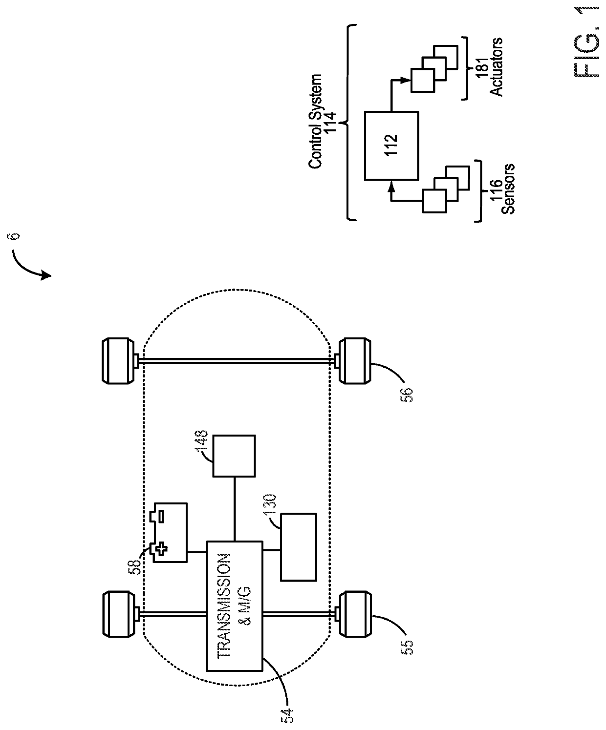
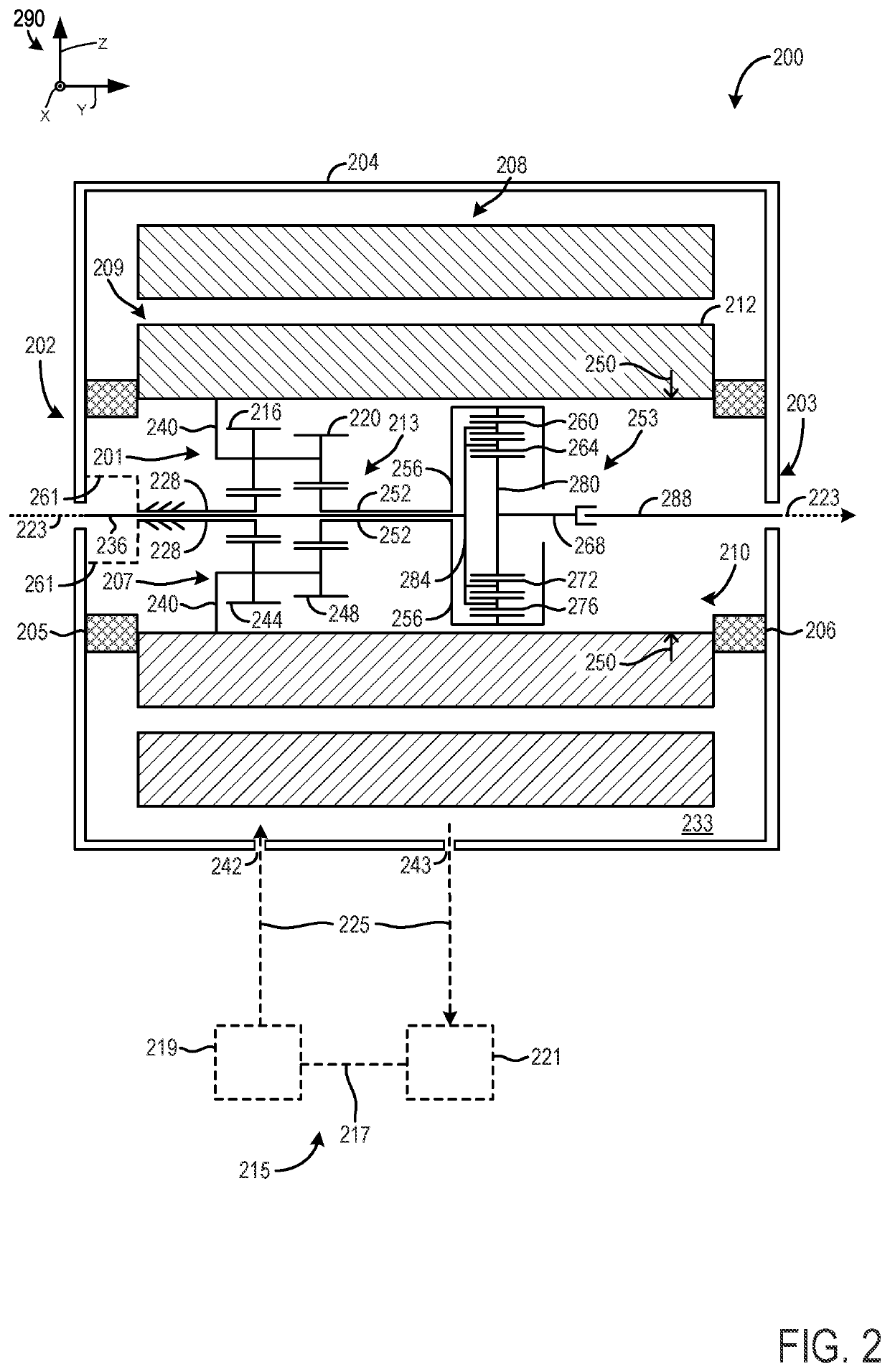
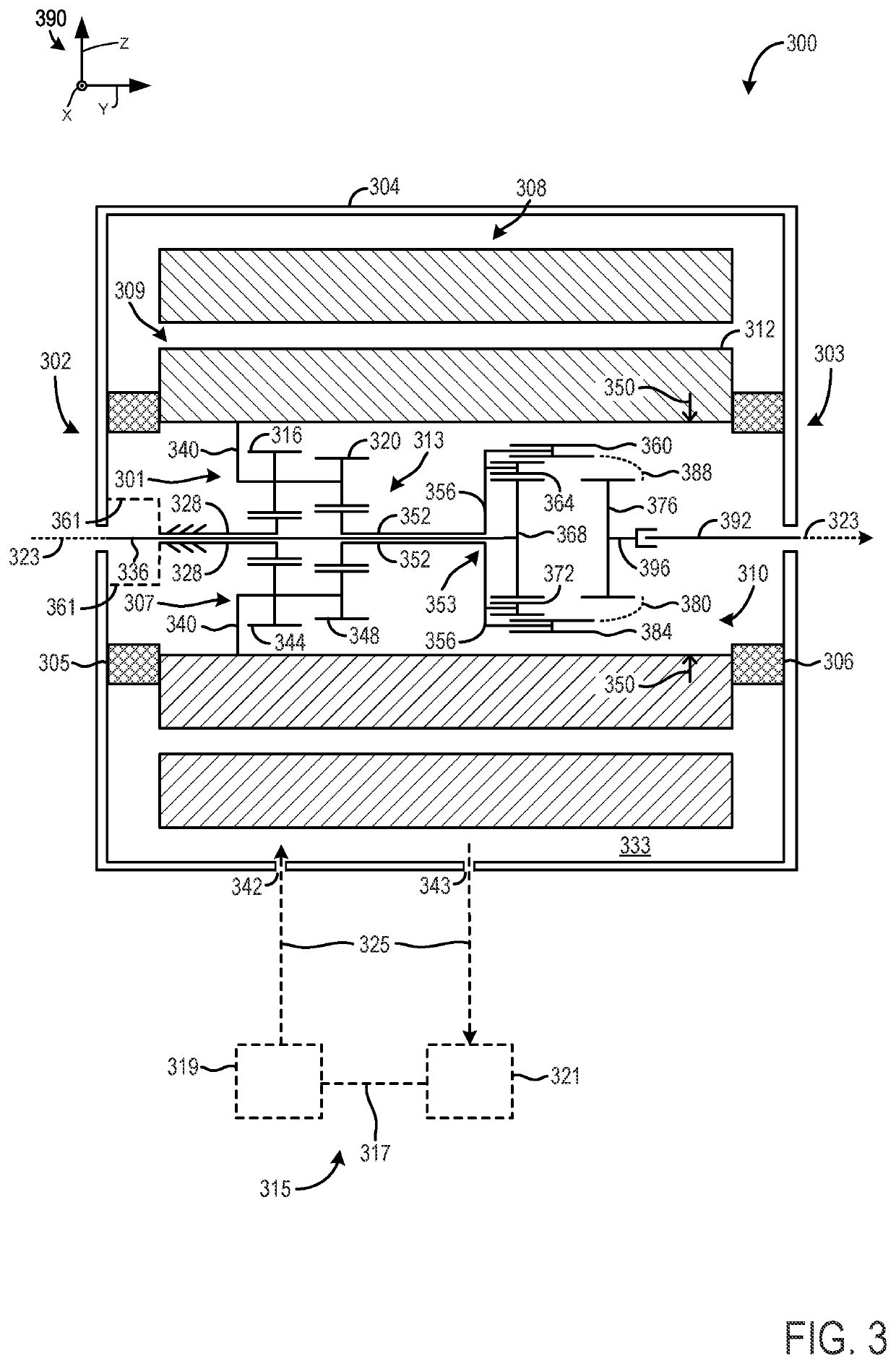
[0019]The following description relates to systems for enclosing a gear box within a rotor of an electric motor. Such systems may be integrated within an electric motor of a vehicle, shown schematically in FIG. 1. A gearbox including compound planetary gear sets for power transmission and a differential gear set may be integrated within the electric motor in a plurality of configurations, as shown in FIGS. 2-4. In particular, FIG. 2 illustrates a first configuration for a compound planetary gear set which may transmit power from the rotor of the electric motor to a planetary differential gear set via a ring gear of the planetary differential gear set. FIG. 3 illustrates a second configuration, which utilizes the same compound planetary gear set illustrated in FIG. 2 to transmit power to a spur differential gear set via input to the carrier of the spur differential gear set. FIG. 4 illustrates a third configuration, in which a differential (either planetary or open) gear set may coup...


PUM


Abstract

Methods and systems are provided for integrating a gearbox into an electric motor. In one example, a system may include enclosing a gearbox containing a planetary gear set and a differential within an envelope of a rotor of the electric motor.

Description

TECHNICAL FIELD[0001]The present description relates generally to systems for integrating a gearbox into a rotor of an electric motor for a vehicle.BACKGROUND AND SUMMARY[0002]In electric vehicles, the powertrain architecture may include a high voltage battery, an electric motor with power controller electronics, and a transmission, which may include a gearbox. Voltage from the battery may be supplied to the electric motor in order for the electric motor to generate power to drive the electric vehicle, which may then be transmitted to the drive wheels via the gearbox.[0003]The electric motor may include a stator and a rotor, with the rotor coupled to one or more output shafts. The stator may be stationary, and may be electrically powered by a voltage source (such as a battery) to generate currents in a plurality of conducting wires included within the stator, which may then generate magnetic fields. In one example, the magnetic fields generated by the stator may induce a current wit...

Claims


Application Information

Patent Timeline
Patent Type & Authority Patents(United States)
IPC IPC(8): F16H37/08B60K17/16B60L15/20F16H3/66F16H48/10F16H57/04B60K17/12B60K1/00
CPCF16H37/082B60K17/12B60K17/16B60L15/2054F16H3/663F16H48/10F16H57/0413B60K2001/001F16H57/0434F16H2048/106F16H2200/2007B60K1/00B60K17/08B60K17/165B60K11/02H02K9/19H02K7/116F16H57/0417F16H57/0424F16H57/043F16H57/0483F16H48/08F16H57/0476F16H48/11
Inventor DEVREESE, THIBAULT
Owner DANA AUTOMOTIVE SYST GRP LLC
Why Eureka
Try Eureka