Synchronous automatic clutch oil supply slip ring suitable for high rotating speed

A synchronous automatic and clutch technology, applied in automatic clutches, clutches, transmission parts, etc., can solve problems such as oil supply difficulties, and achieve the effect of simple structure, simple lubrication system, and reduced requirements.

Pending Publication Date: 2022-03-25
中国船舶重工集团公司第七0三研究所
View PDF0 Cites 0 Cited by
  • Summary
  • Abstract
  • Description
  • Claims
  • Application Information

AI Technical Summary

Problems solved by technology

[0011] The purpose of the present invention is to solve the problem that the existing synchronous automatic clutch suffers from oil supply in high-speed tandem shafting, and provides an oil supply slip ring

Method used


Image

  • Synchronous automatic clutch oil supply slip ring suitable for high rotating speed
  • Synchronous automatic clutch oil supply slip ring suitable for high rotating speed
  • Synchronous automatic clutch oil supply slip ring suitable for high rotating speed

Examples


Embodiment Construction

[0021] The present invention will be further described in detail below in conjunction with the accompanying drawings and specific embodiments.

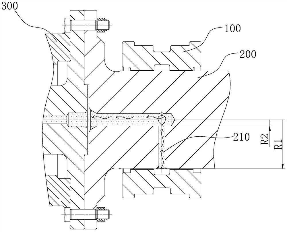
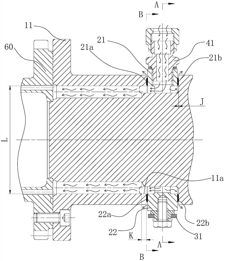
[0022] figure 2 Among them, the oil supply slip ring includes two parts, the slip ring assembly and the slip ring installation groove, the slip ring installation groove is located on the connecting shaft 11 of the synchronous automatic clutch 60, and the remaining parts form the slip ring assembly. A ring groove and an axial oil hole are provided on the connecting shaft (11) of the clutch, and lubricating oil is supplied from the oil supply joint 41, flows through the lubricating oil hole on the connecting shaft 11, and finally enters the synchronous automatic clutch 60. In the working state, the synchronous automatic clutch 60 and its connecting shaft 11 rotate at a high speed, which will cause the radial flow of the fluid on the connecting shaft 11 to become difficult. In order to ensure that the lubricating oil is more effectively...


PUM


Abstract

The synchronous automatic clutch oil supply slip ring comprises an oil supply slip ring body and a slip ring mounting groove, the slip ring mounting groove is located in a synchronous automatic clutch connecting shaft, an axial oil hole is formed in the connecting shaft, the connecting shaft is communicated with the slip ring mounting groove through an oil collecting ring groove, and a slip ring assembly is of a split structure. An oil supply connector and a limiting structure are arranged on the outer side of the slip ring assembly, a tin bronze material is cast on the surface of the portion, matched with the slip ring installation groove, of the slip ring assembly, axial flow channels are evenly distributed in the inner surface of the slip ring and used for lubricating the matched surface, and the slip ring assembly is installed in the slip ring installation groove in a floating mode. And the floating slip ring is limited to rotate along with the rotating connecting shaft through a limiting rod connected with the fixing frame. The oil supply slip ring is suitable for a high-rotating-speed synchronous automatic clutch connected in a unit shaft system in series, the oil supply slip ring is simple in structure, the runner on the rotating connecting shaft is mainly an axial runner, the requirement of the synchronous automatic clutch for oil supply pressure is lowered, and a lubricating system of a unit is simpler.

Description

technical field [0001] The invention relates to an oil supply ring, especially for supplying oil to synchronous automatic clutches working at high rotational speeds. Background technique [0002] Synchronous automatic clutches are widely used as connecting equipment in mechanical systems. The structure of the clutch itself is complex, and its internal transmission gears, ratchets and pawl mechanisms must work under lubricating conditions to ensure long-term reliable operation. Due to the synchronous automatic clutch Structural features, the innermost layer of the clutch where the ratchet pawl is generally arranged, the oil supply structure must be able to supply lubricating oil to the position where the ratchet pawl is located, if the oil supply structure cannot supply oil to the inner depth of the clutch, it needs to be changed The position of the ratchet pawl of the clutch is adapted to the oil supply structure of the clutch, so that the radial design size of the clutch is...

Claims


Application Information

Patent Timeline
Patent Type & Authority Applications(China)
IPC IPC(8): F16D43/04F16H57/04
CPCF16D43/04F16H57/043F16H57/0434F16H57/0473
Inventor 陈克鑫王学志闫泽曲盛楠战庆欣戴维泽张祥王春玲
Owner 中国船舶重工集团公司第七0三研究所
Why Eureka
Try Eureka