Igniter assembly including arcing reduction features

a technology of arcing reduction and igniter, which is applied in the manufacture of sparking plugs, corona discharge, electrical apparatus, etc., can solve the problems of degrading and affecting the quality of the ignition of the mixture of fuel and air, so as to achieve consistent and strong electrical field, significant energy cost savings, and efficient

Active Publication Date: 2014-11-18
FEDERAL MOGUL IGNITION
View PDF18 Cites 1 Cited by
  • Summary
  • Abstract
  • Description
  • Claims
  • Application Information

AI Technical Summary

Benefits of technology

[0010]The inventive igniter provides less arcing and irregular corona in the rollover region due to the corona reducing lip being free of sharp edges, compared to the prior art igniters of Prior Art FIG. 2 and the '942 published application, which include sharp edges in the rollover region. The electrical field emissions from the inventive igniter are more concentrated at the electrode firing end, which allows the igniter to emit a more consistent and stronger electrical field from the electrode firing end, compared to the prior art igniters. For example, the inventive igniter emits a stronger electrical field from the electrode firing end at 30 volts than the prior art igniters of the '942 published application do at 50 volts. Thus, the inventive igniter is more efficient and provides significant energy cost savings relative to the prior art igniters. The inventive igniter also provides a higher quality ignition and better, more stable performance over time than the prior art igniters.

Problems solved by technology

However, as shown in Prior Art FIG. 2, some electrical field emissions often occur in the rollover region, for example in the air surrounding the lip of the shell.
These electrical field emission are referred to as arcing, or irregular corona, which is undesirable for many internal combustion engine applications.
The irregular corona or arcing can degrade the quality of the ignition of the mixture of fuel and air.

Method used


Image

  • Igniter assembly including arcing reduction features
  • Igniter assembly including arcing reduction features
  • Igniter assembly including arcing reduction features

Examples


Embodiment Construction

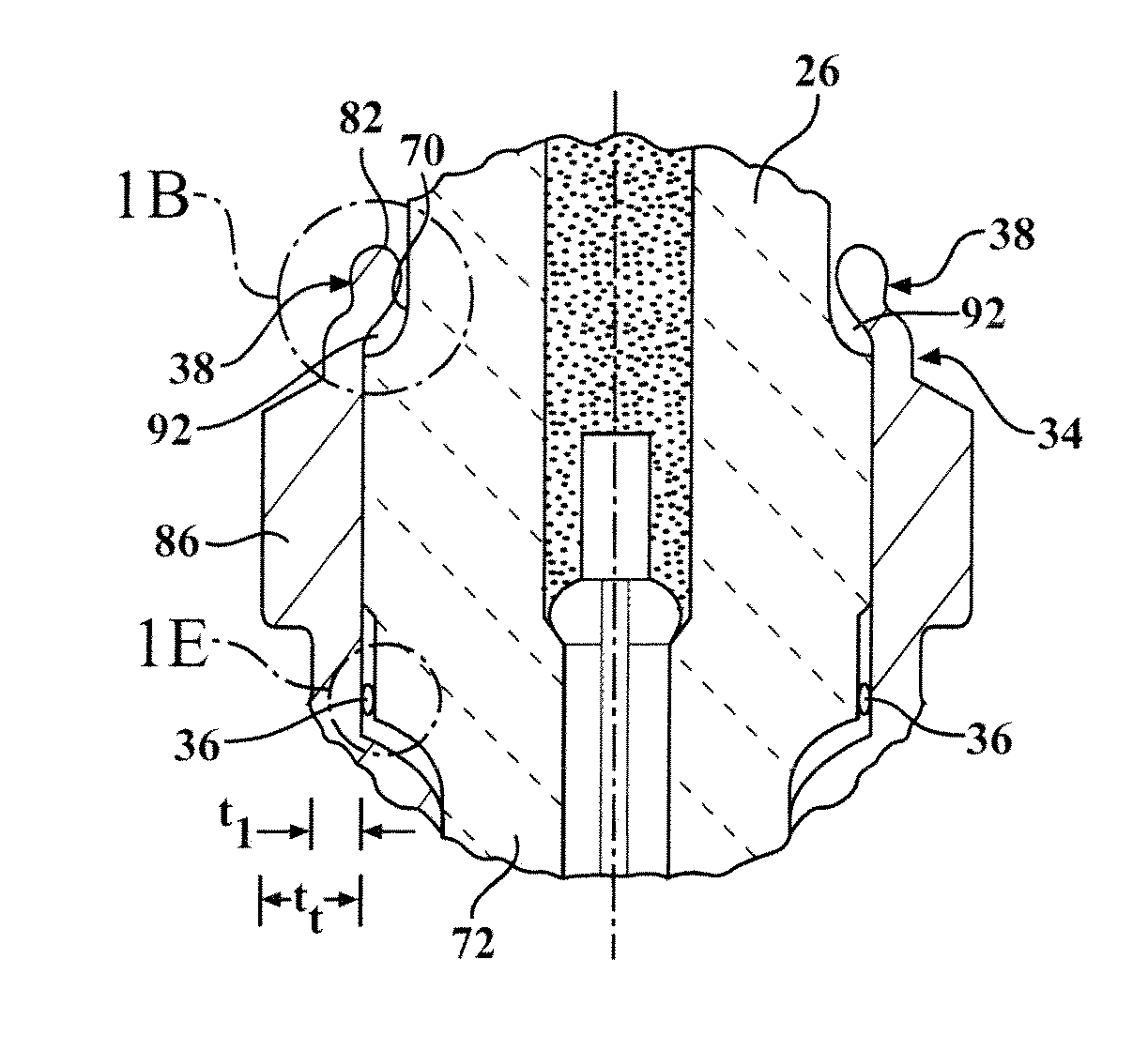
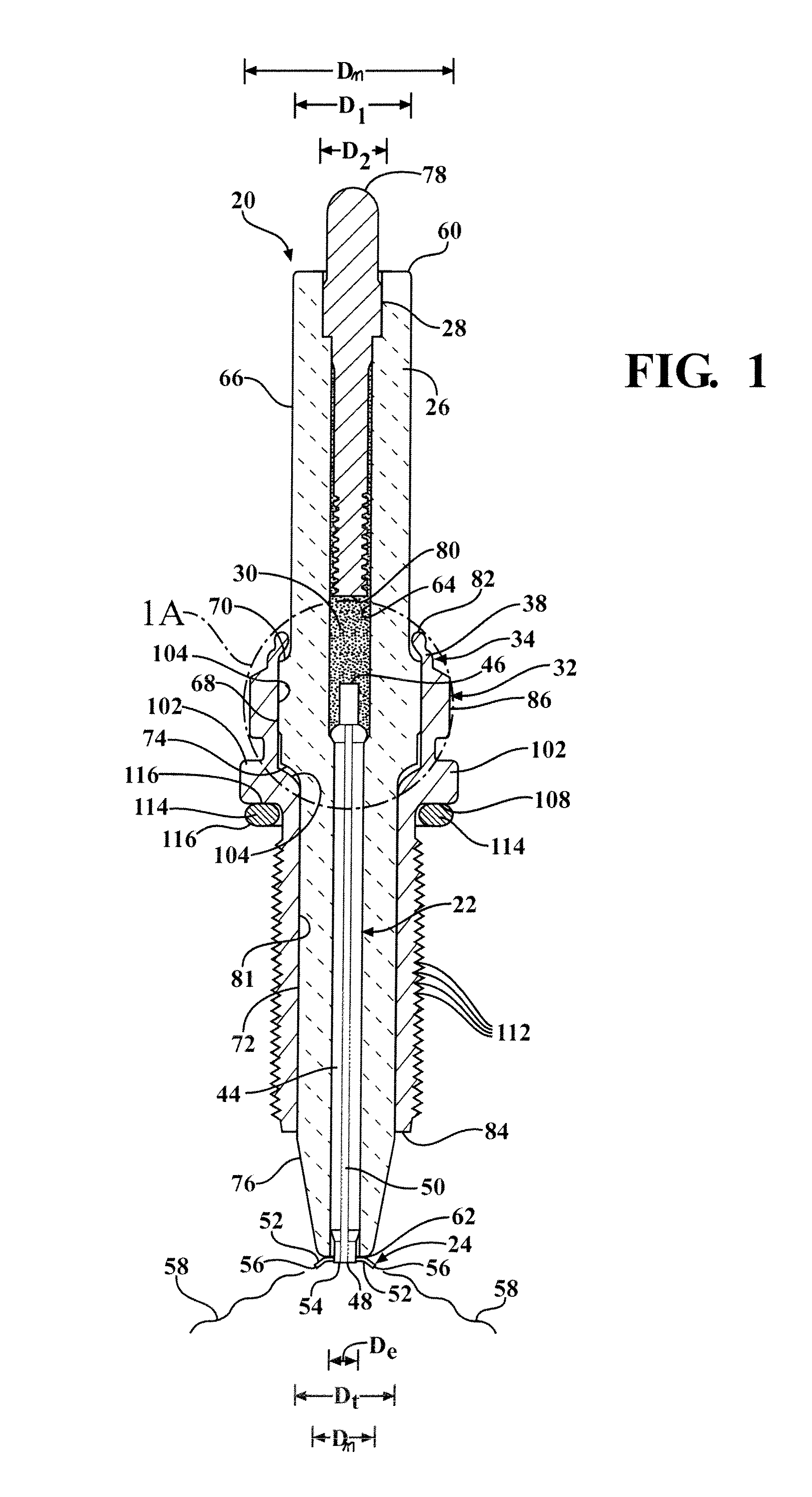
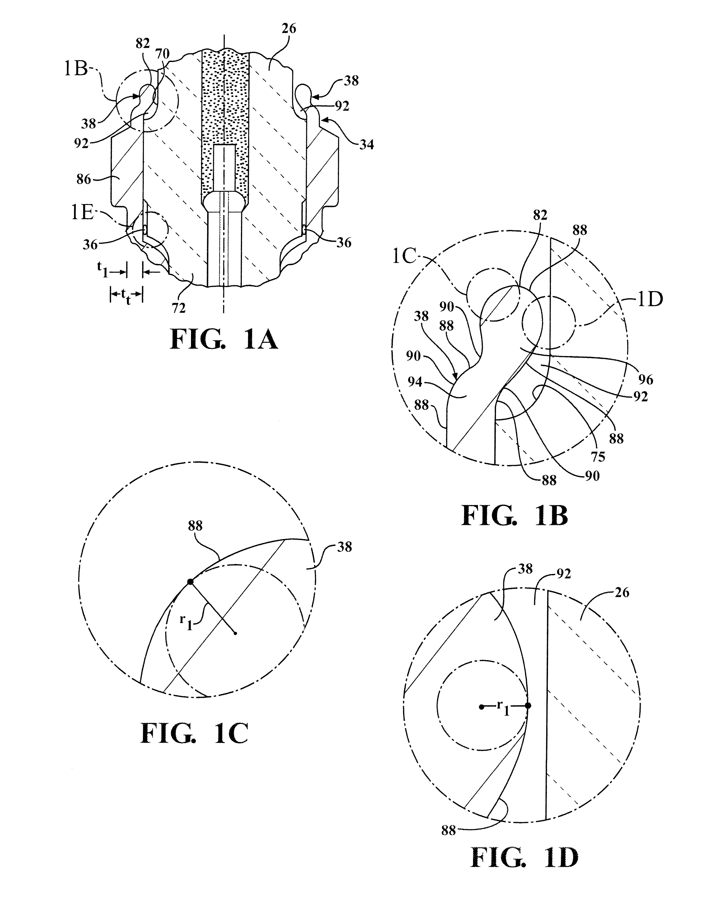
[0033]A corona ignition system includes an igniter 20, as shown in FIG. 1, installed in a cylinder head (not shown) and projecting into a combustion chamber of an internal combustion engine (not shown). The igniter 20 receives a voltage from a power source and emits an electrical field that forms a corona in the surrounding air of the combustion chamber. When fuel is supplied to the combustion chamber, the corona ionizes and ignites the mixture of fuel and air along the entire length of the electrical field. The igniter 20 includes an electrode 22 with a corona enhancing tip 24 and an insulator 26 around the electrode 22. A terminal 28 and a resistor layer 30 are received in the insulator 26, and a shell 32 is disposed around the insulator 26. The shell 32 has an upper flange 34 in a rollover region of the igniter 20. The upper flange 34 comprises a corona reducing lip 38 being free of sharp edges 40 to prevent arcing 42 in the air surrounding the rollover region, unlike lips of the...


PUM

PropertyMeasurementUnit
radiiaaaaaaaaaa
radiiaaaaaaaaaa
radii r1aaaaaaaaaa

Abstract

A corona igniter (20) includes a metal shell (32) with a corona reducing lip (38) spaced from an insulator (26) and being free of sharp edges (40) to prevent arcing (42) in a rollover region and concentrate the electrical field at an electrode firing end (48). The corona reducing lip (38) includes lip outer surfaces (88) being round, convex, concave, or curving continuously with smooth transitions (90) therebetween. The corona reducing lip (38) includes lip outer surfaces (88) presenting spherical lip radii (r1) being at least 0.004 inches. The corona igniter (20) also includes shell inner surfaces (104) and insulator outer surfaces (75) facing one another being free of sharp edges (40).

Description

CROSS REFERENCE TO RELATED APPLICATION[0001]This application claims the benefit of U.S. Provisional Application Ser. No. 61 / 348,330 filed May 26, 2010, the entire contents of which are hereby incorporated by reference.BACKGROUND OF THE INVENTION[0002]1. Field of the Invention[0003]This invention relates generally to a corona discharge igniter for receiving a voltage from a power source and emitting an electrical field for ionizing and igniting a mixture of fuel and air of an internal combustion engine, and methods of manufacturing the same.[0004]2. Description of the Prior Art[0005]An igniter of a corona discharge ignition system receives a voltage from a power source and emits an electrical field that forms a corona to ionize a mixture of fuel and air of an internal combustion engine. The igniter includes an electrode body portion extending longitudinally form an electrode terminal end to an electrode firing end. An insulator is disposed along the electrode body portion, and a shel...

Claims


Application Information

Patent Timeline
Patent Type & Authority Patents(United States)
IPC IPC(8): H01T21/02H01T13/52H01T13/02H01T13/06
CPCH01T13/06H01T21/02H01T13/52H01T19/00Y10T29/49002
Inventor LYKOWSKI, JAMESHAMPTON, KEITH
Owner FEDERAL MOGUL IGNITION
Why Eureka
Try Eureka