Igniter including a corona enhancing electrode tip

a technology of corona enhancing and igniter, which is applied in the manufacture of sparking plugs, anti-theft devices, sparking plugs, etc., can solve the problems of reducing the strength of the electrical field emitted by the electrical erosion the oxidation or chemical corrosion of the corona enhancing tip, etc., to achieve stronger electrical field, lower electrical erosion rate, and lower corrosion rate

Active Publication Date: 2014-07-15
FEDERAL MOGUL IGNITION
View PDF23 Cites 10 Cited by
  • Summary
  • Abstract
  • Description
  • Claims
  • Application Information

AI Technical Summary

Benefits of technology

[0010]The emitting member of the corona enhancing tip can be designed to include a sharp point or radius feature, such as a small spherical radius, for concentrating and emitting a strong electrical field during use of the igniter in a corona ignition system. Since the volume stable material has a lower electrical erosion rate and a lower corrosion rate than the base material, the emitting member can maintain a small spherical radius over time, while the base material begins to erode and corrode to a greater spherical radius. Therefore, the inventive igniter emits a stronger electrical field than the conventional igniter when used in an internal combustion engine for the same amount of time. Also, since the emitting member erodes and corrodes at a lower rate, the inventive igniter provides a more consistent electrical field strength over time compared to the conventional igniter. Thus, the inventive igniter provides a higher quality ignition and better, more stable performance than the conventional igniter over the life of the igniter.
[0011]In addition, the igniter of the present invention emits a stronger electrical field than the conventional igniter at the same voltage. The igniter of the invention emits a stronger electrical field at 30 volts than the conventional igniter does at 50 volts. Thus, the inventive igniter is more efficient and provides significant energy cost savings relative to the conventional igniter.

Problems solved by technology

However, during use of the electrode in the internal combustion engine, the voltage received by the corona enhancing tip over time causes electrical erosion of the corona enhancing tip.
In addition, the corona enhancing tip experiences oxidation or chemical corrosion due to the extreme temperatures, pressures, and constituents of the combustion chamber.
Thus, the strength of the electrical field emitted from the corona enhancing tip decreases and the ignition performance degrades.
Further, over time, the spherical radius of the distal ends may become greater than a spherical radius located between the corona enhancing tip and the insulator, the electric field to be emitted from the wrong point or an irregular ignition position, as shown in FIG. 3, and referred to as arcing, which is undesirable in many situations.
The arcing and / or irregular ignition position also degrades the quality of ignition of the air-fuel mixture.

Method used


Image

  • Igniter including a corona enhancing electrode tip
  • Igniter including a corona enhancing electrode tip
  • Igniter including a corona enhancing electrode tip

Examples


Embodiment Construction

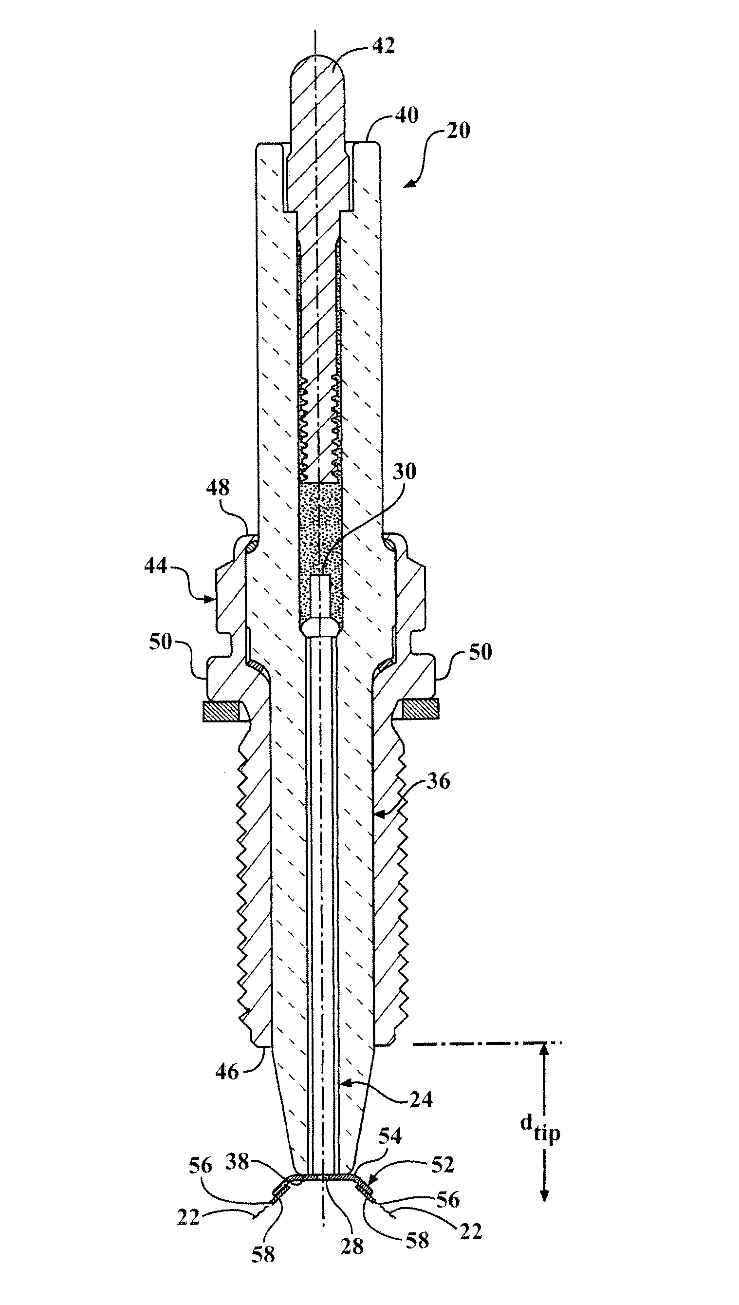
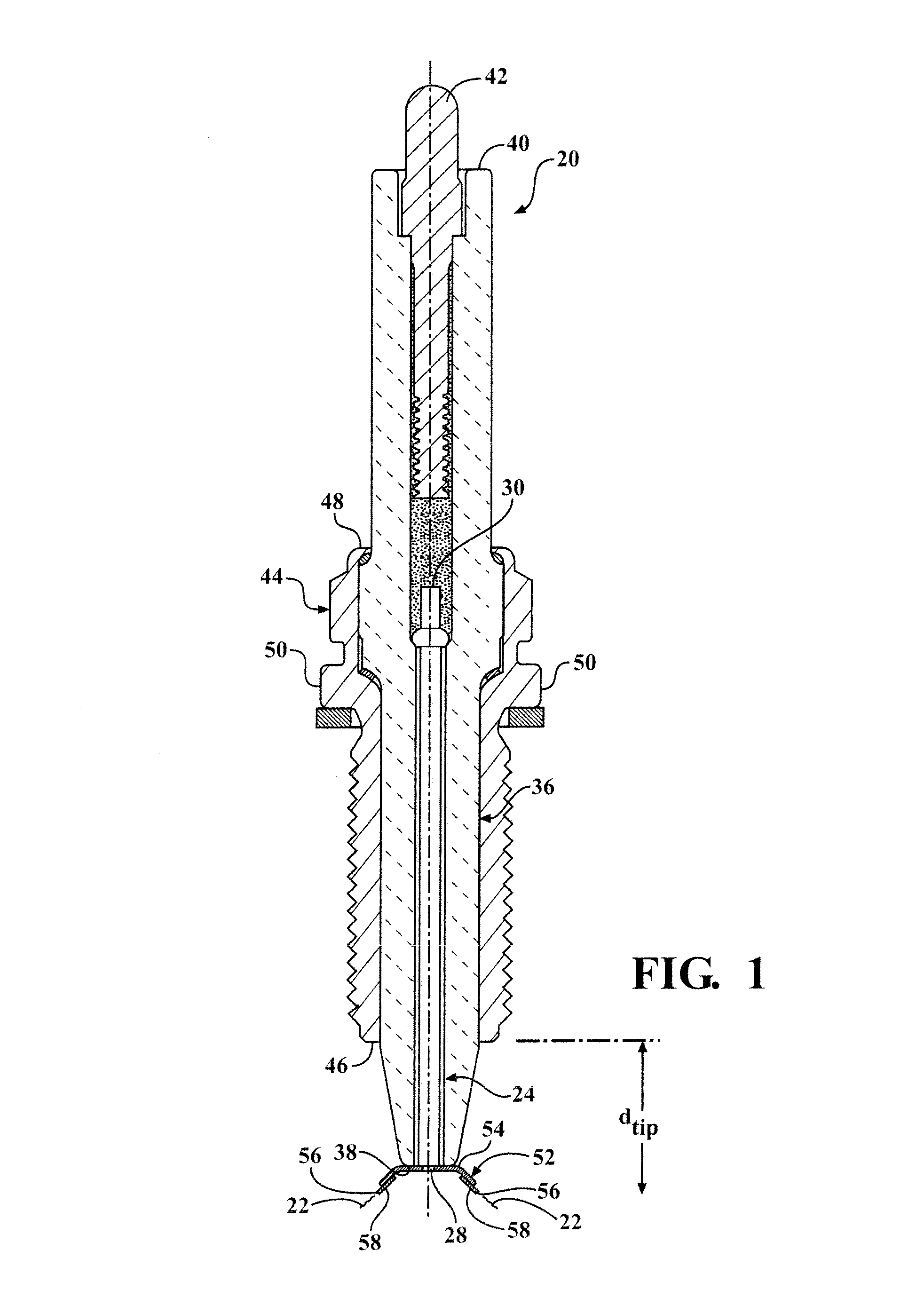
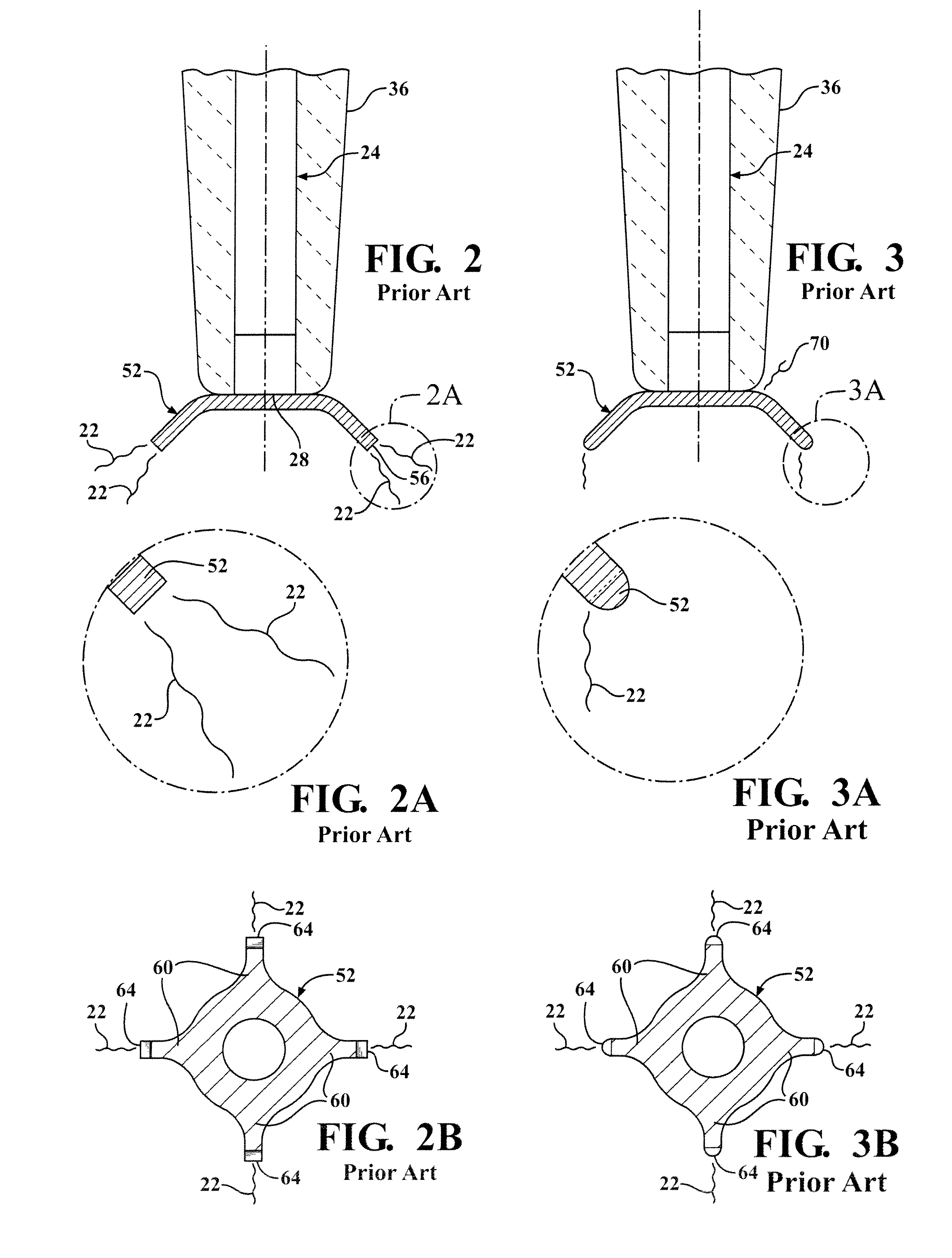
[0084]A corona ignition system includes an igniter 20, as shown in FIG. 1. The igniter 20 receives a voltage from a power source (not shown) and emits an electrical field that forms a corona to ionize and ignite a mixture of fuel and air of a combustion chamber. The electrical field includes at least one streamer 22, as shown in FIG. 1. The mixture of fuel and air ignites along the entire length of the electrical field. The igniter 20 includes an electrode 24 having a body portion 26 extending longitudinally from an electrode firing end 28 to an electrode terminal end 30. The body portion 26 of the electrode 24 can include a bulk portion 32 and a core 34, wherein the core 34 has a heat transfer coefficient greater than the heat transfer coefficient of the bulk portion 32. For example, the bulk portion 32 can be formed of a nickel alloy and the core 34 can be formed of copper. The body portion 26 of the electrode 24 has an electrode diameter De extending generally perpendicular to th...


PUM

PropertyMeasurementUnit
spherical radiiaaaaaaaaaa
melting pointaaaaaaaaaa
angleaaaaaaaaaa

Abstract

An igniter (20) emitting an electrical field including a plurality of streamers forming a corona includes a corona enhancing tip (52) at an electrode firing end (28). The corona enhancing tip (52) includes an emitting member (58) such as a wire, layer, or sintered mass, formed of a precious metal and disposed on a base member (54). The base member (54) is formed of a nickel alloy. The emitting member (58) has a lower electrical erosion rate and chemical corrosion rate than the base member (54). The emitting member (58) presents the smallest spherical radius of the corona enhancing tip (52) at the outermost radial point (56) to concentrate the electrical field emissions and provide a consistently strong electrical field strength over time.

Description

CROSS REFERENCE TO RELATED APPLICATION[0001]This application claims the benefit of U.S. Provisional Application Ser. No. 61 / 323,458, filed Apr. 13, 2010 and U.S. Provisional Application Ser. No. 61 / 432,501, filed Jan. 13, 2011, the entire contents of which are hereby incorporated by reference.BACKGROUND OF THE INVENTION[0002]1. Field of the Invention[0003]This invention relates generally to a corona discharge igniter for receiving a voltage from a power source and emitting an electrical field for ionizing and igniting a mixture of fuel and air of an internal combustion engine, and methods of manufacturing the same.[0004]2. Description of Related Art[0005]Igniters of corona discharge air / fuel ignition systems include an electrode received in an insulator and extending longitudinally from an electrode terminal end to an electrode firing end. The electrode terminal end receives a voltage from a power source and the firing end emits an electrical field to ionize and ignite a mixture of ...

Claims


Application Information

Patent Timeline
Patent Type & Authority Patents(United States)
IPC IPC(8): F02P1/00
CPCH01T13/50H01T13/467H01T21/02F02P9/007Y10T29/49002
Inventor HAMPTON, KEITHWALKER, JR., WILLIAM J.LYKOWSKI, JAMES D.
Owner FEDERAL MOGUL IGNITION
Why Eureka
Try Eureka