
Method for obtaining uplink signal quality of an adjacent cell and method for optimizing handoff

a technology of uplink signal quality and adjacent cells, applied in the field of wireless cellular communication systems, to achieve the effect of reducing the failure rate of handover

Inactive Publication Date: 2014-11-18
ZTE CORP
View PDF17 Cites 7 Cited by
  • Summary
  • Abstract
  • Description
  • Claims
  • Application Information

AI Technical Summary

Benefits of technology

This approach reduces handover failure rates by considering uplink signal quality and detecting coverage mismatches, improving user experience and network performance by optimizing handover decisions and coverage adjustments in real-time.

Problems solved by technology

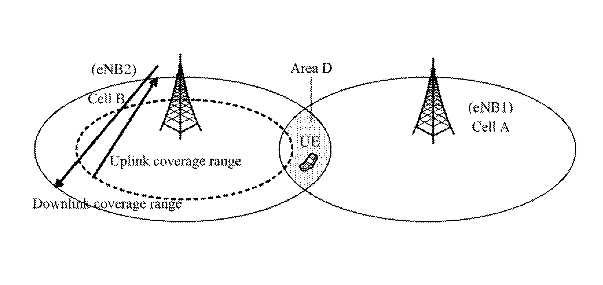
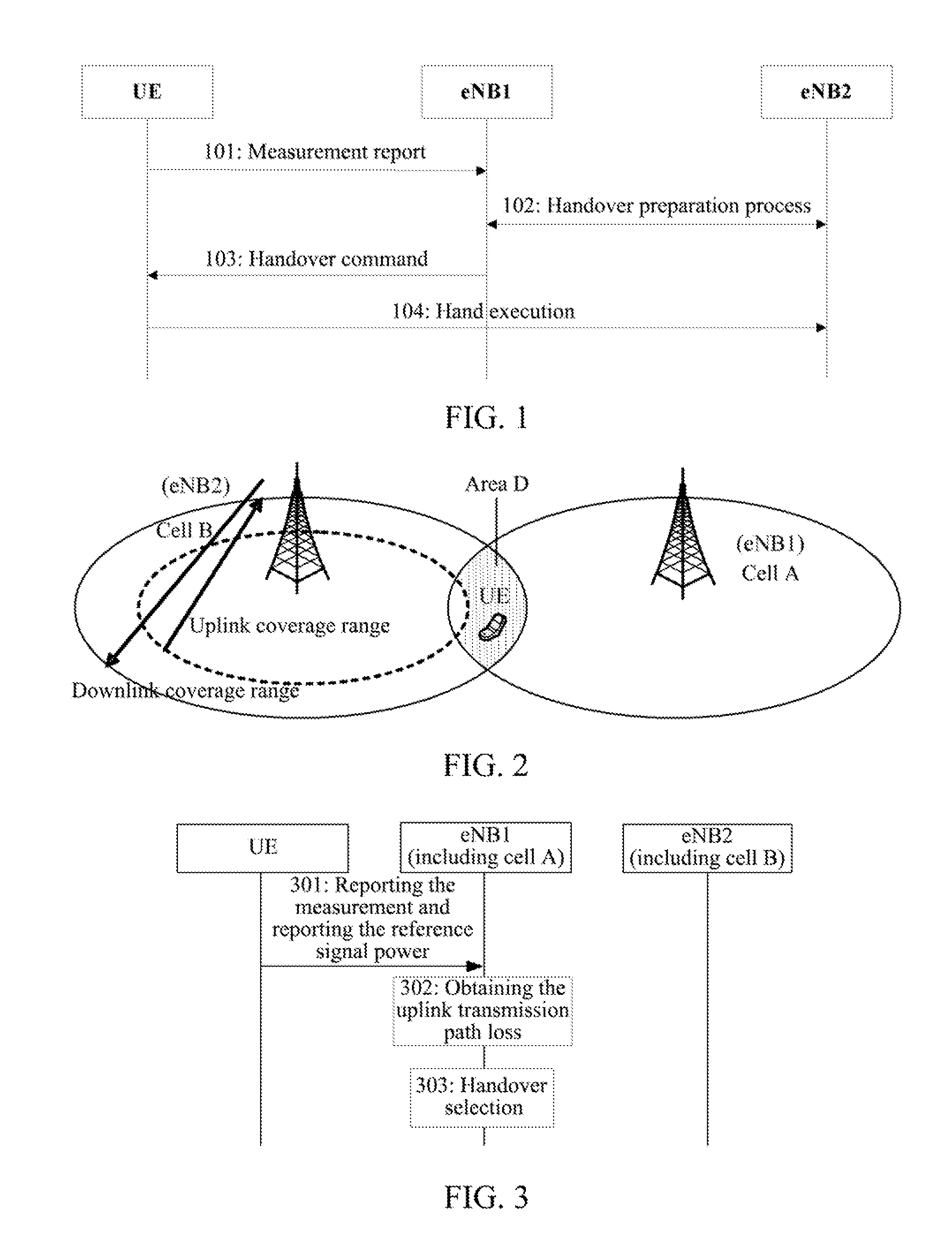
As shown in FIG. 2, the cell A and cell B dominated by the eNB1 and eNB2 are neighbor cells, however the uplink and downlink coverage of the cell A has a problem, and the uplink coverage is smaller than the downlink coverage, and at this time, when the UE which is located in the cell A moves to the area D shown in the figure, the measurement of the UE can not be reported due to lacking the uplink, and finally UE drops the call and so on, and thus how to detect the area with this problem is also a problem to be solved.

Method used


Image

  • Method for obtaining uplink signal quality of an adjacent cell and method for optimizing handoff
  • Method for obtaining uplink signal quality of an adjacent cell and method for optimizing handoff
  • Method for obtaining uplink signal quality of an adjacent cell and method for optimizing handoff

Examples


embodiment one

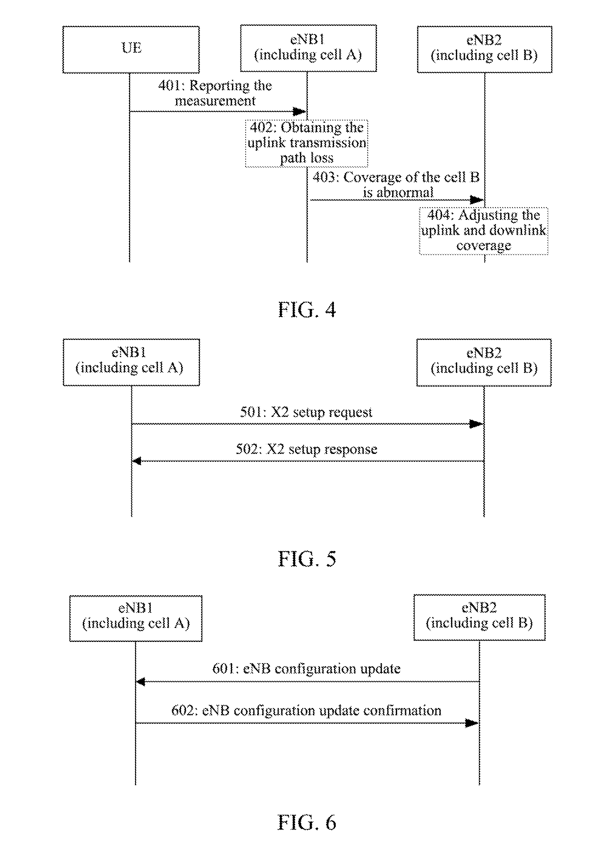
[0056]As shown in FIG. 3, eNB1 makes the handover optimization selection according to the measurement report result and the uplink signal quality of the UE in the neighbor cell, which particularly comprises:

[0057]step 301, the UE located in the cell A reports the measurement result to the eNB1, the measurement result includes the measurement result of the UE for the signal of the cell B, and also reports the reference signal power “ReferenceSignalPower” information of the cell B to the eNB1 at the same time;

[0058]step 302, the eNB1 calculates the downlink transmission path loss PLDL of the UE in the cell B according to the reference signal power “ReferenceSignalPower” of the cell B and the measurement result of the UE for the signal of the cell B, and since the difference between the uplink path loss and the downlink path loss is very small in the wireless transmission process, thus the calculated downlink transmission path loss PLDL is approximately taken as the uplink transmission...

embodiment two

[0062]FIG. 4 shows the flow chart of the method for optimizing the coverage proposed in the present invention, and the method comprises:

[0063]steps 401-402, the same as the steps 301-302;

[0064]step 403, if the uplink transmission path loss PLUL of the UE in the cell B calculated by the eNB1 in step 402 is greater than the configured second threshold ThreshCOVERAGE, it is denoted that the uplink coverage and downlink coverage of the neighbor cell are not matched, namely the uplink is not enough, or the downlink coverage of the neighbor cell is too large. At this time, the eNB1 notifies the eNB2 that the coverage is abnormal through the X2 interface message.

[0065]Step 404, the eNB2 takes this message into its own statistical data after receiving the message, and makes the input of subsequently adjusting the self uplink and downlink coverage according to the statistical data.

[0066]Furthermore, in step 403, the eNB1 also can notify the OAM that the coverage of the eNB2 is abnormal, and ...


PUM


Abstract

A method for obtaining an uplink signal quality of a neighbor cell includes: a serving Evolved Node B obtaining a downlink transmission path loss of current user equipment in said neighbor cell according to a reference signal power of said neighbor cell and a measurement report result of said user equipment for said neighbor cell, taking said downlink transmission path loss as an uplink transmission path loss of said user equipment in said neighbor cell, and estimating the uplink signal quality of said user equipment in said neighbor cell according to said uplink transmission path loss. Correspondingly, the present invention further provides a method for optimizing handover and an evolved node B.

Description

TECHNICAL FIELD[0001]The present invention relates to the wireless cellular communication system, and particularly, to a method for obtaining an uplink signal quality of a neighbor cell in a Long Term Evolution (LTE) mobile communication system and a method for optimizing handover.BACKGROUND OF THE RELATED ART[0002]The LTE network is composed of Evolved Universal Terrestrial Radio Access Network (E-UTRAN) base stations, namely Evolved Node B (eNB), and an Evolved Packet Core (EPC) of the evolved packet switching center. The coverage range of the LTE system is composed of cellular cells dominated by a plurality of eNBs.[0003]When one user moves in the cellular cell system, the user will unavoidably move from one cell to another cell, which causes the cell re-selection or cell handover. One simple example is that, when one user is calling and moves from the coverage range of a certain cell to the coverage range of another cell, the user is required to automatically carry out handover ...

Claims


Application Information

Patent Timeline
Patent Type & Authority Patents(United States)
IPC IPC(8): H04W36/00
CPCH04W36/0016H04W36/0083H04W36/0094H04W24/02H04W36/0085
Inventor HE, FENG
Owner ZTE CORP
Learn More