Surface identification system and method, object having an identification code pattern, and code reading apparatus for reading the object

a surface identification and object technology, applied in the field of surface identification systems and methods, can solve the problems of data chip being put wrong on an incorrect surface, affecting the identification accuracy of the object, and high cost of using rfid technology, etc., and achieves the effect of easy to be torn off and colorful

Inactive Publication Date: 2014-11-25
LAU PING CHEUNG MICHAEL
View PDF9 Cites 10 Cited by
  • Summary
  • Abstract
  • Description
  • Claims
  • Application Information

AI Technical Summary

Benefits of technology

[0008]Another object of the invention is to provide an identification code pattern which affords additional structural and operating advantages.
[0034]The present invention provides an alternative solution and technology for the detection and / or identification of a surface and / or different faces on a three dimensional object by modulating the light reflection, for instance infrared reflection directly from a surface by means of a three-dimensional identification code pattern on the surface, such that an inexpensive IR reader / decoder can be used to read and decode the code pattern in order to identify the surface and / or the different faces on the object, without the need of installing additional electronic circuit and / or further surface treatment, such as printing and / or labeling to a surface for that purpose.
[0035]According to the present invention, the code pattern is embedded onto a surface of an object when the object is formed or manufactured, therefore it helps to minimize and / or eliminate the need for any addition of parts and / or assembly, which not only lowers the production costs, more importantly it can eliminate any errors during the assembly as mentioned above for the other solutions. Unlike the bar code method which typically requires printing the bar code / codes in black and white, the present invention can virtually take on any color.

Problems solved by technology

Use of the RFID method requires a separate RFID data chip for each surface of the object, therefore the cost for using the RFID technology is relatively high.
In addition the data chip needs a mechanical assembly process in order to be placed onto each of the faces, therefore errors can be introduced during the assembly process.
For example, the data chip can be put wrong onto an incorrect surface, not to mention the extra labor cost for the mechanical assembly.
Again this requires an additional assembly process which can add costs and is possible to introduce errors, not to mention other problems such as a case that the bar code label is relatively easily torn off from a surface, making the identification to be a failure.

Method used


Image

  • Surface identification system and method, object having an identification code pattern, and code reading apparatus for reading the object
  • Surface identification system and method, object having an identification code pattern, and code reading apparatus for reading the object
  • Surface identification system and method, object having an identification code pattern, and code reading apparatus for reading the object

Examples


Embodiment Construction

[0055]While this invention is illustrated and described in preferred embodiments, the invention may be produced in many different configurations, sizes, forms and materials.

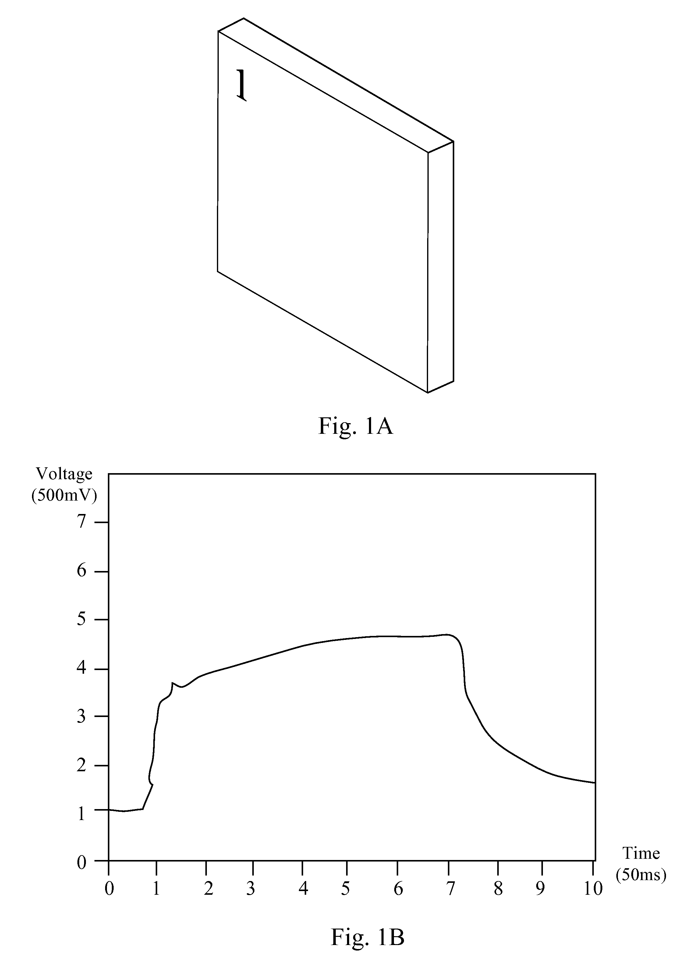
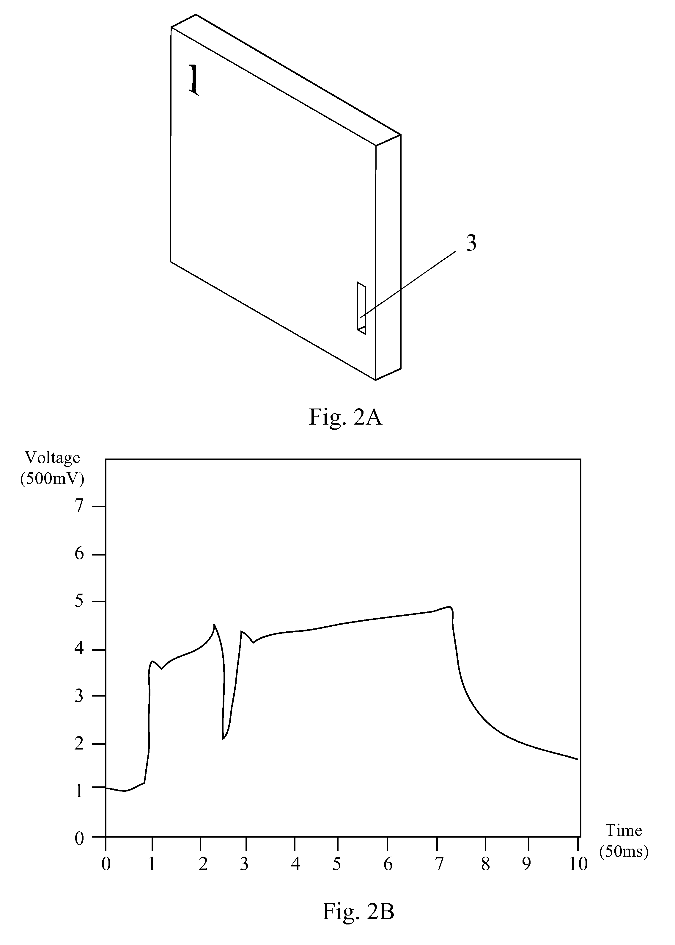
[0056]When a light source is pointed at a surface, be it a metallic and / or a plastic surface, a portion of the light will be reflected from the surface. The amount of light reflection depends on the physical properties of the surface. Generally, a matt or darker colored surface reflects less light while a glossy and / or lighter colored surface reflects more light. If a light-receiving sensor such as a photo transistor and / or photo diode is brought close to the surface while a light source is irradiating light onto it, the light receiving sensor can receive the light reflected from the surface. The amount of light received by the light receiving sensor is basically in proportion to the distance between the sensor and the reflective surface and to the light reflective property of the surface such as color and glossi...


PUM


Abstract

The present invention provides A surface identification system comprising: at least one identification code pattern comprising a plurality of recesses, through holes and / or projections formed on an code area of a first surface, the identification code pattern being made to correspond to the first surface or a second surface; and a code reading apparatus for reading the identification code pattern, the code reading apparatus being capable of irradiating light rays towards the code area, receiving reflected light rays reflected from the code area to read out the identification code pattern according to an amount of the reflected light rays from each of the plurality of recesses, through holes and / or projections, and indicating a correspondence between the identification code pattern and the first surface or the second surface. The invention also relates to a surface identification method, an object having an identification code pattern and a code reading apparatus for reading the object.

Description

FIELD OF THE INVENTION[0001]This invention relates generally to a system and a method for identification of a surface, and more particularly, to a system and a method for identification of a surface by reading an identification code pattern formed on the surface through light modulation induced by the identification code pattern. This invention also relates to an object having the identification code pattern and a code reading apparatus for reading the object.BACKGROUND OF THE INVENTION[0002]In industrial and / or consumer product applications, some electronic means are required to detect different faces on a three dimensional object for the purposes of identification and / or automating sorting, for example to identify the 2 faces of a tile, or to identify the 6 individual faces on a cube and etc. RFID (Radio Frequency Identification) technology can be used to identify the different faces of the object. In the RFID method, RFID data chip with different ID codes can be put onto the unde...

Claims


Application Information

Patent Timeline
Patent Type & Authority Patents(United States)
IPC IPC(8): G06K5/00G06K7/14G06K19/06G06K19/063G06K1/20
CPCG06K5/00G06K7/1408G06K1/20G06K19/06159G06K19/063
Inventor LAU, PING, CHEUNG, MICHAEL
Owner LAU PING CHEUNG MICHAEL
Why Eureka
Try Eureka