

Rebound control material
a technology of bounding control and material, applied in the direction of roadway safety arrangements, traffic restrictions, roads, etc., can solve the problems of vehicle itself being crushed and bearing the brunt of the impact, vehicle may rebound back onto the highway, device damage or destruction,
- Summary
- Abstract
- Description
- Claims
- Application Information
AI Technical Summary
Benefits of technology
Problems solved by technology
Method used
Image

Examples
example 1
Material
[0085]A hyperelastic material was prepared using an MDI-polyether quasi-prepolymer system. The prepolymer had a free isocyanate content of approximately 13.3%. A long chain polyether component based on polytetramethylene glycol was utilized. The polyol had OH# of approximately 56. The short-chain diol utilized was hydroquinone bis(2-hydroxyethyl) ether (HQEE) and accounted for approximately 40% by weight of the total hydroxyl-containing components of the mixture.
[0086]Reactive components were combined in a proportion that provided approximately 5% excess of isocyanate groups in the total mixture. A typical polyurethane catalyst package was utilized to accelerate the reaction and shorten demold time. Catalyst loading was adjusted to provide a gel time of approximately three minutes.
[0087]A three component liquid casting machine equipped with precision gear pumps to accurately meter components and a dynamic mix head to obtain adequate mix quality and heating capability were us...
example 2
Testing Material
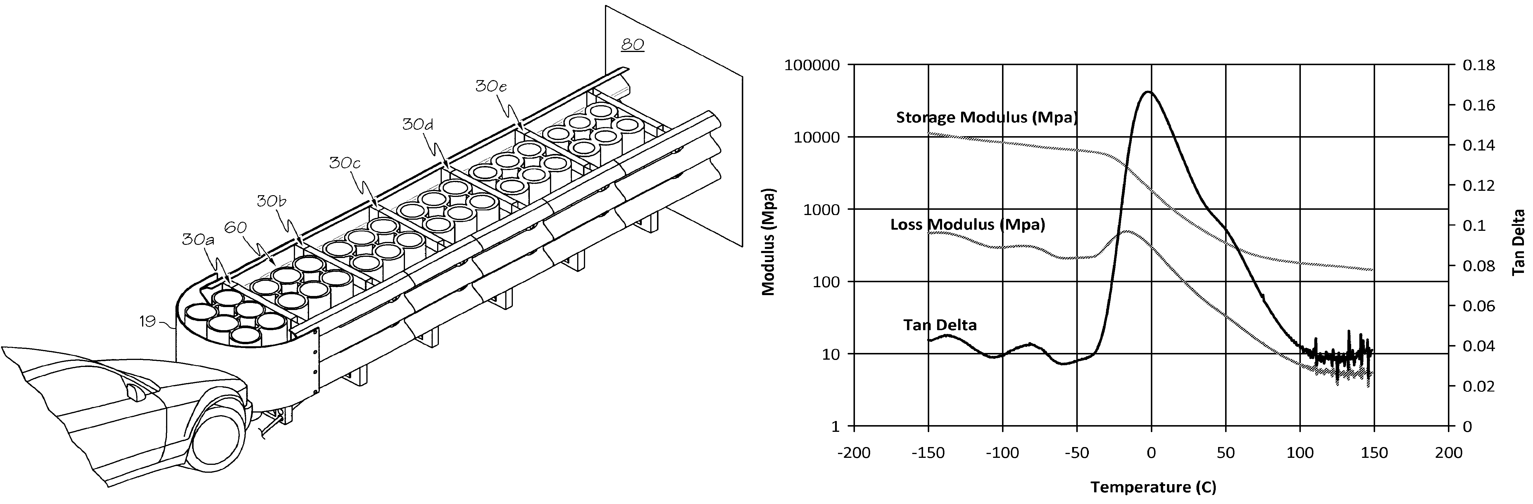
[0088]A material for thermoset, cast polyurethane components for use in making the hyperelastic elements in the impact attenuator system was formulated. DMA tests were conducted using a TA Instruments Q800 DMA system to measure the storage modulus E′, the loss modulus E″ and the mechanical loss (damping), tan δ over a temperature range of −150 to 150° C. changing at a rate of 3° C. per minute, and at 1 Hz. The results of those tests are shown in FIG. 10. Tan δ may be greater than 0.05 and of relatively constant value. Tan δ may be greater than 0.1 and of relatively constant value. The tan δ for the material made in Example 1 is between 0.10 and 0.14 throughout the operating temperature range of −15 to 45° C. The glass transition temperature (Tg) onset, as determined by the storage modulus, was measured at approximately −27° C., and there was no melting transition present.
[0089]Samples were prepared from a formulation having the physical properties of: a storage modul...
example 3
Impact Attenuator Component
[0094]Further large scale dynamic testing of an impact system incorporating the hyperelastic material showed desirable properties where the material demonstrated high levels of energy absorption, controlled rebound and recoverability. A prototype component of the impact system was prepared from the material in Example 1.
[0095]The prototype component was impacted by a 2,857 lb (1,296 kg) semi-rigid cart head-on at the centerline of the cart and test article at a speed of 20.8 mph (33.5 km / hr). FIG. 16 shows the test article (a) just prior to impact and (b) at maximum dynamic displacement. FIG. 17 is a photograph of the test article taken after the test which shows the recoverability of the component. FIG. 14 shows a graph of force vs time of the impact event measured by an instrumented wall at the back of the prototype component. FIG. 15 shows a graph of velocity vs. time of the impact event measured from an accelerometer mounted onto the vehicle.
PUM
| Property | Measurement | Unit |
|---|---|---|
| temperatures | aaaaa | aaaaa |
| temperatures | aaaaa | aaaaa |
| tan δ | aaaaa | aaaaa |
Abstract
Description
Claims
Application Information