Active adaptive gyrostabiliser control system

a control system and gyrostabiliser technology, applied in the direction of gyroscopes, vessel safety, floating buildings, etc., can solve the problems of limited performance, instability of the roll resisting torque produced by the flywheel, and limited stabilising effect during more common events

Active Publication Date: 2014-12-02
VEEM
View PDF11 Cites 7 Cited by
  • Summary
  • Abstract
  • Description
  • Claims
  • Application Information

AI Technical Summary

Benefits of technology

[0016]Preferably the actuator applies only a braking precession control torque to the gyrostabiliser flywheel, as this eliminates the requirement for external motive power to be supplied to the actuator to operate the system and this is considered advantageous. Accordingly, the precession control torque may be a resistive control torque, such that the actuator does not provide motive power to the flywheel about a precession axis. Alternatively, the actuator responsive to the control signal for applying a precession control torque to the gyrostabiliser flywheel may provide a precession axis damping control signal that acts only to resist the induced precession motion of the flywheel. Alternatively or additionally, the control signal may be a flywheel precession axis resistance gain, said gain being gradually decreased to allow the flywheel to develop as much induced precession as possible whilst not exceeding a predefined maximum precession angle range. Alternatively, a driving precession control torque may be applied.
[0018]Preferably when it is estimated that a derived process control variable (based on the precession angle and / or its derivatives) will exceed a predefined limit, the AGC incrementally increases the gain by a set amount or by an amount proportional to an estimated overshoot, so as to provide an increased braking precession control torque to the gyrostabiliser flywheel precession axis with the aim of preventing the defined precession angle limit from being exceeded. The control system may run a predictive model of said derived process control variable to allow the AGC gain to be varied based on an estimated future state of the derived process variable.
[0025]applying a precession control torque to the gyrostabiliser flywheel responsive to the control signal whereby, in use, active adaptive control of the vessel motion based only on the precession of the gyrostabiliser flywheel can be achieved.
[0040]One of said flow paths may provide a pressure relief valve that provides over-pressure protection for the hydraulic circuit in the event that the pressure drop created across either the fixed or manually adjustable valve or the electronically controlled valve exceeds a predefined safe level.

Problems solved by technology

This causes instability in the roll resisting torque produced by the flywheel as it momentarily becomes zero.
If the resistance to precession is great enough to prevent induced over-precession during peak input events, the stabilising effect during more common events will be severely limited.
Although the performance of these prior art systems was remarkable in some wave environments, (up to 95% roll reduction), the precession control systems were not able to adapt to varying wave conditions, so the performance was limited by simplistic precession torque controls.
As a result, there have been proposed more complex control systems for gyrostabilisers to provide improved vessel motion attenuation performance over a wide range of operating conditions.
If a process control variable becomes unavailable to the control system due to sensor error, loss of system power or other failure, the active control system will cease to operate.
For actively driven gyrostabilisers, this will result in immediate loss of the stabilising influence of the gyrostabiliser, which risks the safe and / or comfortable operation of the vessel.
With the provision of increasing numbers of sensors to permit more complex gyrostabiliser control algorithms that are more responsive to changing sea states and vessel motion, the risk of one or more sensors failing is increased.

Method used


Image

  • Active adaptive gyrostabiliser control system
  • Active adaptive gyrostabiliser control system
  • Active adaptive gyrostabiliser control system

Examples


Embodiment Construction

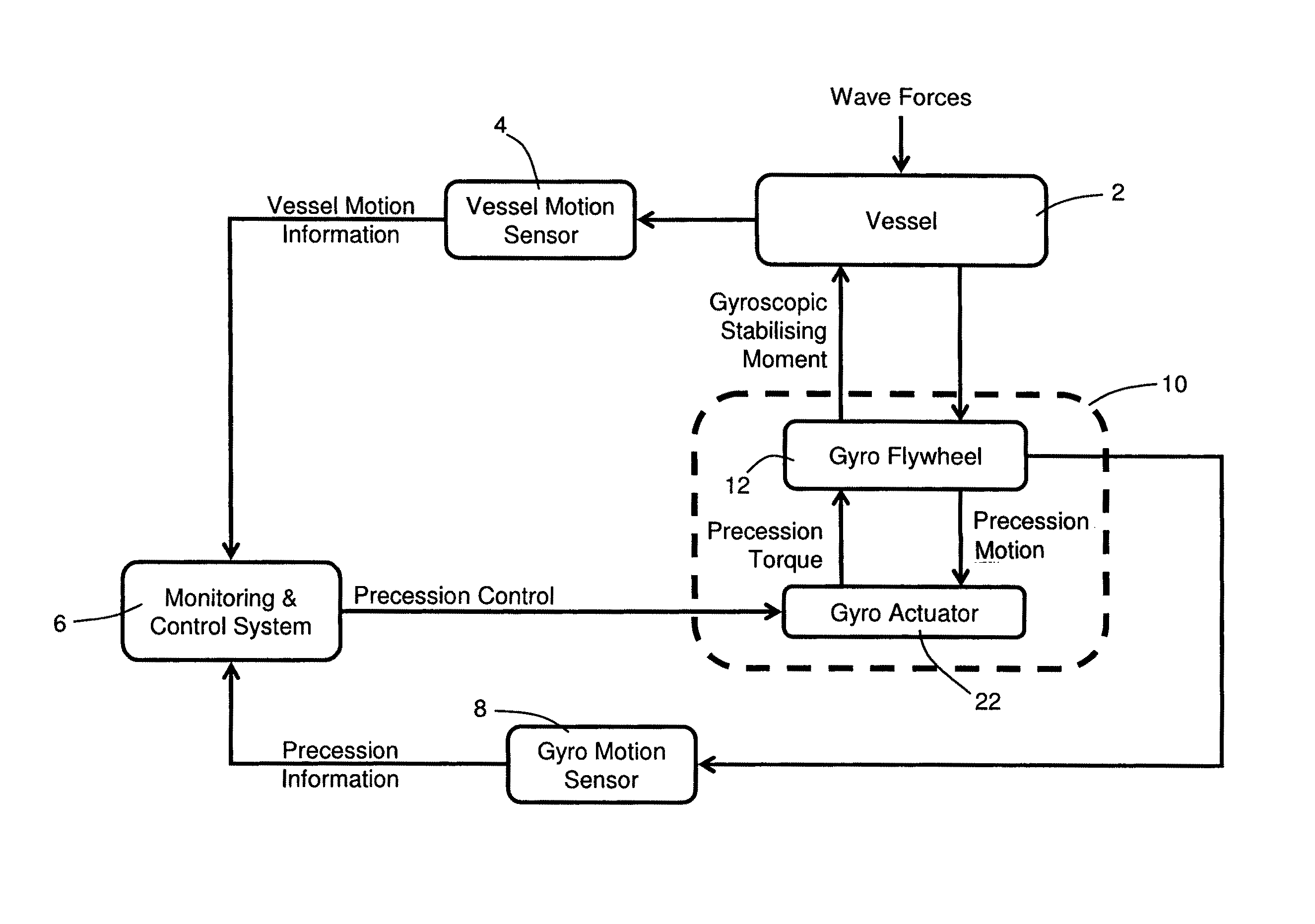
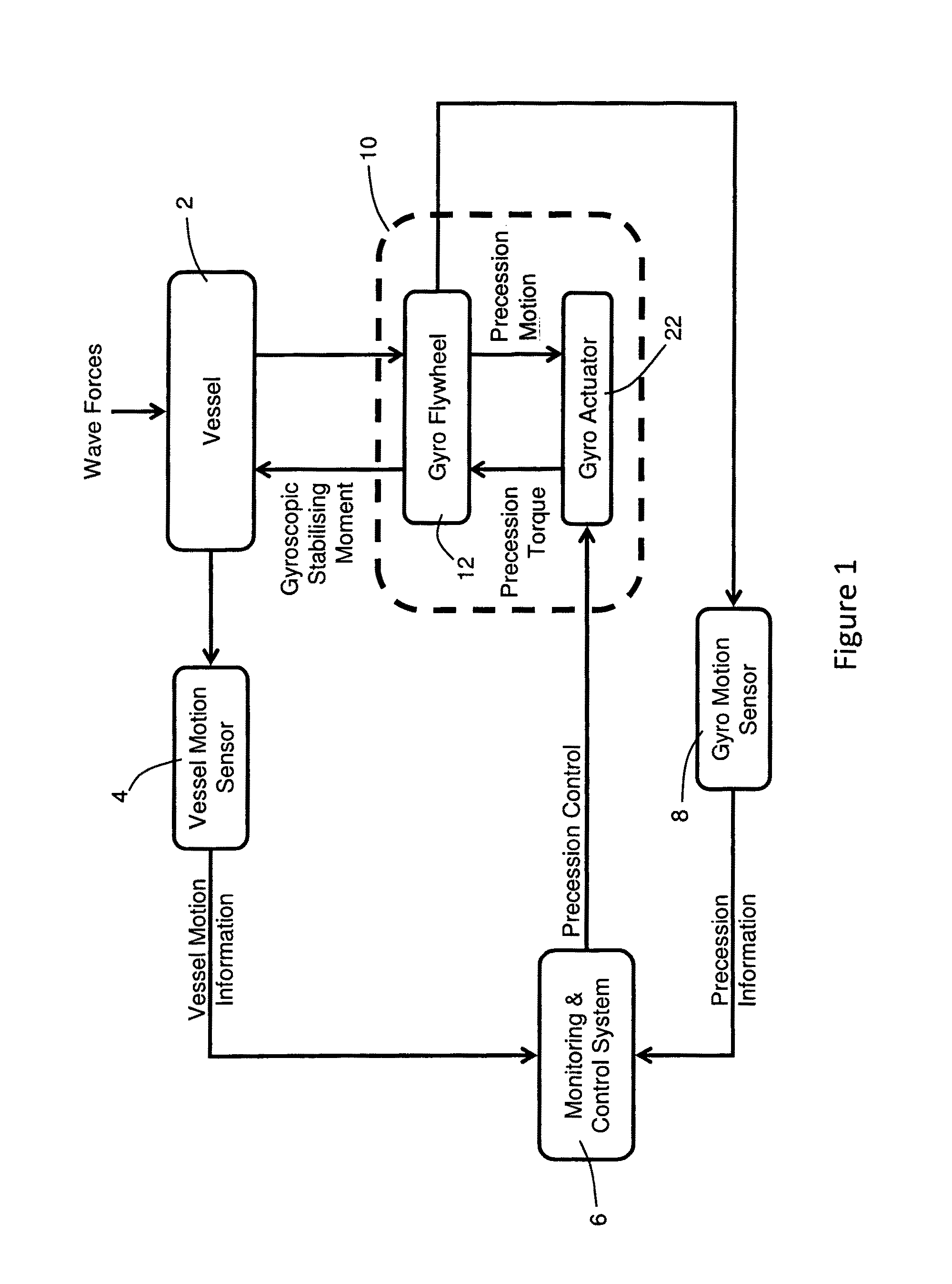
[0058]Throughout this specification the term “vessel” refers to a marine floating platform, typically a boat, yacht, barge, ship or submarine, which is subject to oscillating motion due to environmentally induced excitation forces that produce roll motion. The term “roll motion” refers to the rolling motion of the vessel including any or all derivatives thereof, but more broadly refers to any oscillating motion of the vessel that it is desired to be attenuated. FIG. 1 illustrates in simplified form the typical architecture of a gyrostabiliser control system utilising both vessel motion and precession axis measurements as process control variables. The motion of the vessel 2 is transferred to the flywheel 12 of a gyrostabiliser 10, and the precession action of the flywheel 12 produces a gyroscopic stabilising moment that counteracts the moment induced by the waves. Gyroscopic flywheels have two degrees of freedom: spin and precession. By conservation of angular momentum due to spin a...


PUM


Abstract

A gyrostabilizer control system and method for stabilizing marine vessel motion based on precession information only. The control system employs an Automatic Gain Control (AGC) precession controller (60). This system operates with a gain factor that is always being gradually minimized so as to let the gyro flywheel (12) develop as much precession as possible—the higher the precession, the higher the roll stabilizing moment. This continuous gain change provides adaptation to changes in sea state and sailing conditions. The system effectively predicts the likelihood of maximum precession being reached. Should this event be detected, then the gain is rapidly increased so as to provide a breaking precession torque. Once the event has passed, the system again attempts to gradually decrease the gain.

Description

CROSS-REFERENCE TO RELATED APPLICATIONS:[0001]This application is the U.S. National Stage of International Patent Application No. PCT / AU2011 / 000168 filed on Feb. 17, 2011, which claims priority to Australian Patent Application No. 2010900643 filed on Feb. 17, 2010, the disclosures of which are hereby incorporated by reference in their entireties.FIELD OF THE INVENTION[0002]The present invention relates to a gyrostabiliser control system and method for stabilising marine vessel motion induced by wave and environmental excitation forces that produce roll motion and relates more particularly, though not exclusively, to an active adaptive gyrostabiliser control system and method.BACKGROUND TO THE INVENTION[0003]When a gyrostabiliser is used in a marine vessel to attenuate rolling motion, the rolling motion of the vessel induces flywheel precession that in turn produces a torque that opposes the rolling motion. This means that the induced flywheel precession is always in an appropriate p...

Claims


Application Information

Patent Timeline
Patent Type & Authority Patents(United States)
IPC IPC(8): B63B39/04G01C21/18
CPCB63B39/04G01C21/18G05D1/0875
Inventor STEINMANN, PAUL DOUGLASPEREZ, TRISTAN
Owner VEEM
Why Eureka
Try Eureka