Supercharge Your Innovation With Domain-Expert AI Agents!

Deck panel for cargo carrying vehicle

a cargo carrying vehicle and deck panel technology, applied in the field of deck panels, can solve the problems of difficult handling of each panel, large footprint, and difficulty in adjusting the thickness of the plywood that has a sufficient thickness to support heavy loads

Active Publication Date: 2014-12-02
ANCRA INTERNATIONAL CORPORATON
View PDF22 Cites 3 Cited by
  • Summary
  • Abstract
  • Description
  • Claims
  • Application Information

AI Technical Summary

Problems solved by technology

While plywood panels are functionally adequate, the use of plywood has a number of drawbacks.
Plywood that has a thickness adequate to support heavy loads is generally quite heavy, particularly when stored outside where it is prone to absorbing moisture through rain, snow, etc.
Aside from the weight, each panel, by reason of its large footprint, is difficult to handle, particularly for a single individual who must somehow effect a grasp on the edges thereof while maneuvering the panel to elevate it, transport it, and place the same strategically upon the load beams.
As a result, the lower surfaces on the installed plywood panels have a tendency to shift relative to underlying beams.
Plywood panels are also difficult to maneuver individually from a stacked relationship.
That is, while the plywood panels stack compactly in a face-to-face relationship, it may be difficult to grasp the individual panels to separate them from the stack.
Plywood panels are also prone to degradation, particularly after repeated use.
Plywood that is not adequately dried tends to buckle.
Plywood also has a tendency to splinter, which not only affects its integrity but also creates weakened areas and loose splinters that may interfere with comfortable handling by a user.
Plywood may also weaken or fail after repeated bending under load.
Generally, since plywood is made with laminated layers, a progressive compromising of the individual layers may lead to weakening or failure.
Still further, plywood is inconvenient to dispose of in an ecologically appropriate manner once it has reached the end of its useful life.
Commonly, the spent plywood panels will simply be stacked in a manner whereby, in significant accumulation, they become obtrusive and unsightly.
Many of the above problems are still contended with using panels injection molded from plastic, and the like.
However, this keying structure interferes with compact stacking of the panels where they are staged or stored.
Conventional configurations of these injection molded panels typically make them less than convenient to handle, particularly for a single individual.
For a single individual, this is not a convenient process.
While injection molded panels generally may have a longer anticipated useful life than those made from plywood in most applications, eventually the panels will be worn or replaced, which necessitates disposal of the old panels.
Commonly, materials used to injection mold the panels are not biodegradable.
Thus, disposal of large volumes of molded panels has a detrimental environmental impact.
These polymers tend to be brittle at low temperatures.
The panels made with these polymers have thus been prone to fracturing and breakage when utilized in cold environments.
Early failure of these panels also has a significant economic impact that makes them impractical in certain environments and for certain heavy loading.
Another problem with prior art panels, made either from plywood or molded material, is that they are generally not stackable in a manner that facilitates bulk transportation, as around a yard using a forklift, or the like.
Since plywood stacks face-to-face, there is no practical way to introduce the leading ends on the forks on a lift between panels without inflicting damage thereupon.
While molded panels have raised elements that produce spacing between adjacent stacked panels, the inability of the panels to consistently nest in a predetermined manner results in their being unstably stacked.
Attempts to introduce forks between adjacent panels may cause upper panels to fall off of the lifted stack.
In spite of the fact that the transportation industry utilizes very large numbers of these panels, the industry has contended with the above problems because there have been no viable commercial designs that are capable of effectively meeting the many design criteria.

Method used


Image

  • Deck panel for cargo carrying vehicle
  • Deck panel for cargo carrying vehicle
  • Deck panel for cargo carrying vehicle

Examples


Embodiment Construction

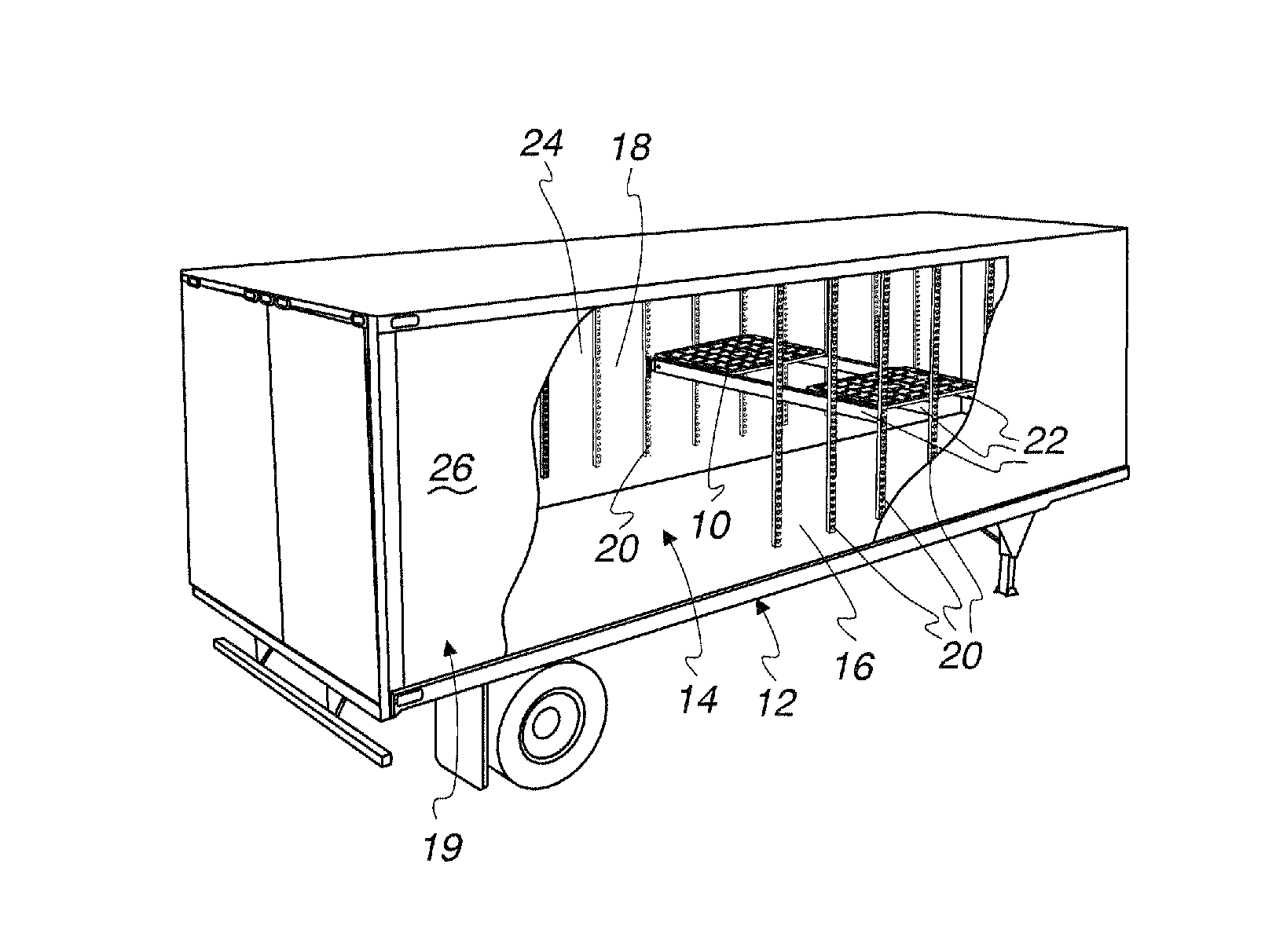
[0058]As seen in FIG. 1, the invention is directed to a deck panel 10 that is used in a cargo carrying vehicle 12 having a storage space 14 for cargo. The storage space 14 is bounded by a floor surface 16 and a surface 18 on a peripheral, upstanding wall 19. The peripheral wall surface 18 is reinforced by vertically extending posts 20.

[0059]Elongate load beams 22 span between spaced side walls 24, 26, making up a part of the wall 19, and are releasably connected to the reinforcing posts 20 thereon at a desired height. The load beams 22 are oriented with their lengths horizontal and in a substantially parallel relationship.

[0060]The deck panel 10 is shown in FIG. 1 operatively engaged with three spaced, underlying load beams 22 of like construction. The load beams 22 are spanned by the deck panel 10 and provide vertical support therefor. Typically, more than two load beams 22 will be spanned by, and engage, each deck panel 10, depending upon the weight and nature of the supporting ca...


PUM


Abstract

The combination of a cargo carrying vehicle and a deck panel. The cargo carrying vehicle has a storage space and a plurality of parallel elongate load beams in the space. A lower surface of the deck panel engages each of the first and second elongate load beams. The body has a plurality of discrete components depending from the lower surface that are abuttable to the load beams to thereby limit shifting of the deck panel. The upper surface has at least a first opening and the lower surface has at least a first complementary projection. A second deck panel, the same as the first deck panel, can be stacked on the first deck panel so that a corresponding at least first projection on the second deck panel extends into the at least first opening to maintain the first and second deck panels in a predetermined stacked relationship.

Description

BACKGROUND OF THE INVENTION[0001]1. Field of the Invention[0002]This invention relates to deck panels that span, and are supported upon, adjacent load beams above a floor on a cargo carrying vehicle.[0003]2. Background Art[0004]Load beams are commonly used in cargo carrying vehicles to define a support for cargo above a main, upwardly facing floor surface. Exemplary load beams are shown in U.S. Pat. No. 7,578,644. The load beams span the width of the storage space and have ends that are releasably connected, one each, to spaced side walls that bound the storage volume. The beams are placed at controlled fore-and-aft intervals to provide stable support for spanning deck panels upon which cargo is placed.[0005]Designers of these panels focus on a number of different criteria. First and foremost, the panels must have the ability to stably support cargo and so that it is maintained in place without significant shifting occurring relative to the underlying beams with an associated vehicl...

Claims


Application Information

Patent Timeline
Patent Type & Authority Patents(United States)
IPC IPC(8): B62D33/02B65D19/00B60P1/00
CPCB60P1/00
Inventor KNOX, HOWARD T.BAKER, PAUL W.
Owner ANCRA INTERNATIONAL CORPORATON
Features
  • R&D
  • Intellectual Property
  • Life Sciences
  • Materials
  • Tech Scout
  • Unparalleled Data Quality
  • Higher Quality Content
  • 60% Fewer Hallucinations
Learn More