Miter coupling and method

a technology of miter coupling and metal support structure, applied in the field of mit, can solve the problems of inherently weak joints and inherently limited strength of joints, and achieve the effects of less time-consuming and laborious, less expensive, and stronger joints

Inactive Publication Date: 2014-12-02
TRIVETTE ROGER BLAINE
View PDF59 Cites 4 Cited by
  • Summary
  • Abstract
  • Description
  • Claims
  • Application Information

AI Technical Summary

Benefits of technology

[0006]This device and process allows a pair of square metal tubes to be attached, end to end, at any desired angle in a manner that is less expensive, less time consuming and labor intensive, and which provides a stronger joint.

Problems solved by technology

This procedure, which is used during the production of many types of products, such as supports, frames, scaffolding, and the like, is very labor intensive and results in a joint that has inherently limited strength.
However, this method leaves an open end of the second tube exposed (thus requiring an end cap in many applications), further requires a grinding of the weld, and again results in an inherently weak joint.

Method used


Image

  • Miter coupling and method
  • Miter coupling and method
  • Miter coupling and method

Examples


Embodiment Construction

. INVENTION

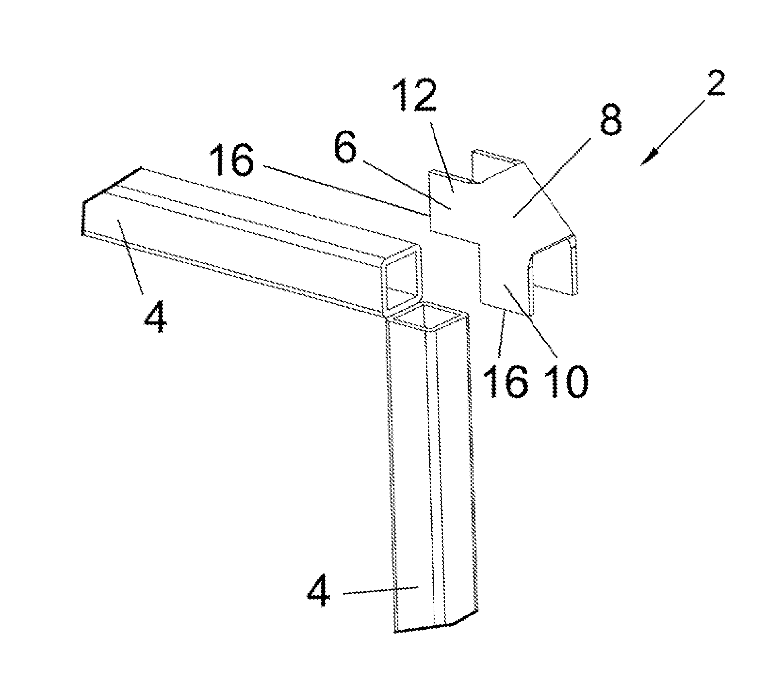
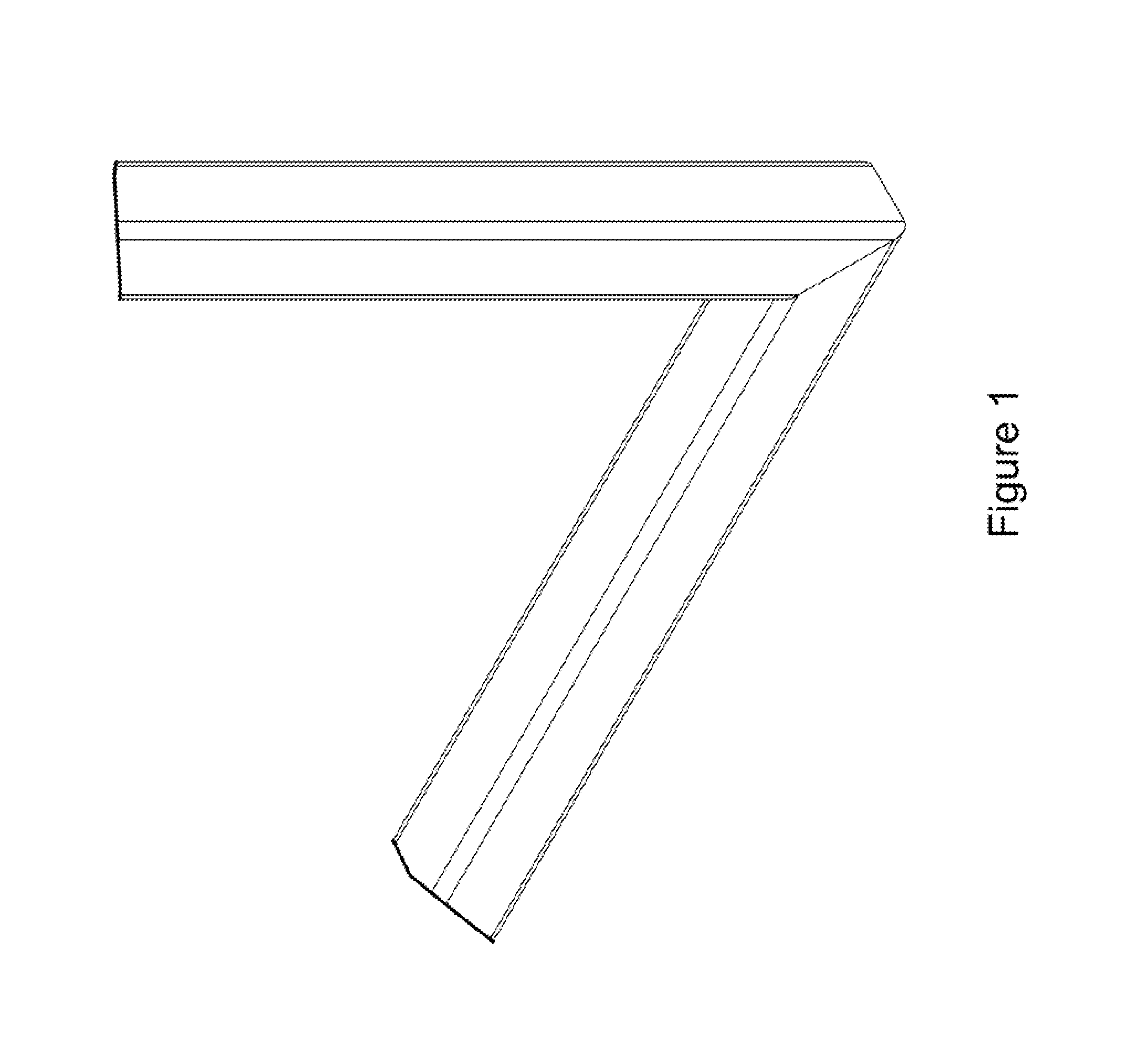
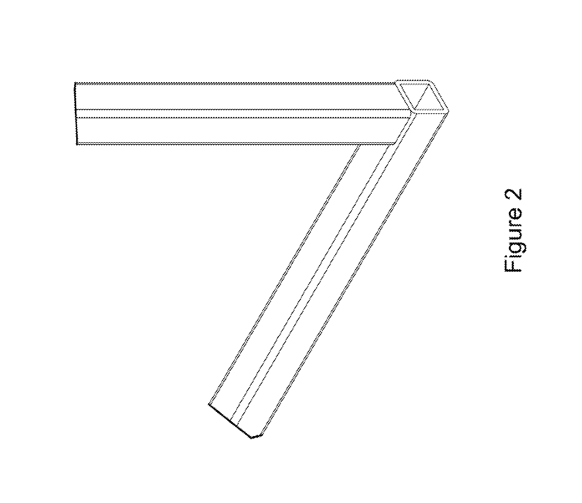
[0016]The present invention includes a miter coupling device and method for joining together two square metal tubes at a desired angle. FIGS. 1 and 2 illustrate common methods for joining square metal tubes at a 90 degree angle. FIG. 1 shows two square metal tubes, each having one end cut at a 45 degree angle, wherein the square metal tubes are joined to form a 90 degree angle. In order to join the square metal tubes in accordance with FIG. 1, the tubes are cut at the proper angle, welded around the four seams, and then the welds are ground, down to form a smooth seam. This method is time consuming, labor intensive and expensive. Cutting the tubes to the proper angles consumes valuable time and labor, as does the grinding operation to smooth the welds for a proper finish. Additionally, the strength of the joint produced by this method is limited. FIG. 2 shows an alternate joint and method, wherein the square metal tubes are cut in a transverse direction with respect to th...


PUM

PropertyMeasurementUnit
45 degree angleaaaaaaaaaa
degree angleaaaaaaaaaa

Abstract

A miter coupling and method for using the miter coupling to join a pair of square metal tubes at a desired angle using a welding process. The miter coupling, in a preferred embodiment, comprises a single piece of metal formed into a shape that is adapted to receive the ends of two square metal tubes at a desired angle. The miter coupling is shaped to form a pair of parallel elbow members, where the elbow members are formed into a desired angle, and the elbow members are interconnected by a cross support.

Description

BACKGROUND OF THE INVENTION[0001]The present invention relates generally to techniques and devices for welding or otherwise joining metal support structures together. More specifically, the present invention includes a miter coupling and a method of using such a miter coupling to join together a pair of metal tubes at a desired angle.[0002]Typically, when charged with the task of joining together a pair of metal tubes having a square cross section (square metal tubes), a metal worker must cut an end of each tube to the desired angle, weld the tour sides of the tubes together, and then grind the weld down so that the joint has a smooth outer surface. This procedure, which is used during the production of many types of products, such as supports, frames, scaffolding, and the like, is very labor intensive and results in a joint that has inherently limited strength. Alternatively, when it is necessary to join the square metal tubes to form a 90 degree angle, instead of cutting each tube...

Claims


Application Information

Patent Timeline
Patent Type & Authority Patents(United States)
IPC IPC(8): B25G3/00B23K31/02B23K33/00
CPCB23K31/022B23K2201/28B23K33/006Y10T403/725F16B12/50Y10T403/72Y10T403/4602Y10T403/478B23K2101/28F16B2200/67F16B2200/65
Inventor TRIVETTE, ROGER BLAINE
Owner TRIVETTE ROGER BLAINE
Why Eureka
Try Eureka