
Exercise device

a technology of exercise device and exercise device, which is applied in the direction of pneumatic massage, sport apparatus, breathing protection, etc., can solve the problems of many known exercise device, prone to breakage, and many of the known exercise devi

Inactive Publication Date: 2014-12-02
EGAN
View PDF9 Cites 18 Cited by
  • Summary
  • Abstract
  • Description
  • Claims
  • Application Information

AI Technical Summary

Benefits of technology

The patent text talks about a type of exercise device that uses negative pressure to improve workouts. By using the device, users can exercise with part of their body in a negative pressure environment, which leads to better results and reduces the amount of time required to exercise. The device also includes a motor that is cooled effectively to prevent damage and make the user experience more comfortable. Overall, the patent aims to provide an improved and comfortable exercise experience.

Problems solved by technology

Although there are numerous benefits to this type of exercise device, there are problems with many of the known exercise devices.
Unfortunately, many of the known exercise devices are relatively unreliable in operation and are prone to breaking down.
This results in a significant amount of downtime and represents a significant cost to the proprietor of the exercise device.
When the exercise device is not operational, it cannot be used to generate revenue for the proprietor and furthermore a repair person must be paid to repair the exercise device.
This lack of reliability also leads to mistrust in the machines thereby presenting a barrier to more widespread uptake and popularity of the exercise devices.
One of the main culprits of downtime is the electronics components in the exercise device failing.
This problem is further exacerbated by the fact that infra-red bulbs are also often used within the vacuum chamber as part of a complementary therapy, thereby further increasing the temperature within the chamber and increasing the likelihood of the electronics components failing.

Method used


Image

  • Exercise device
  • Exercise device
  • Exercise device

Examples


Embodiment Construction

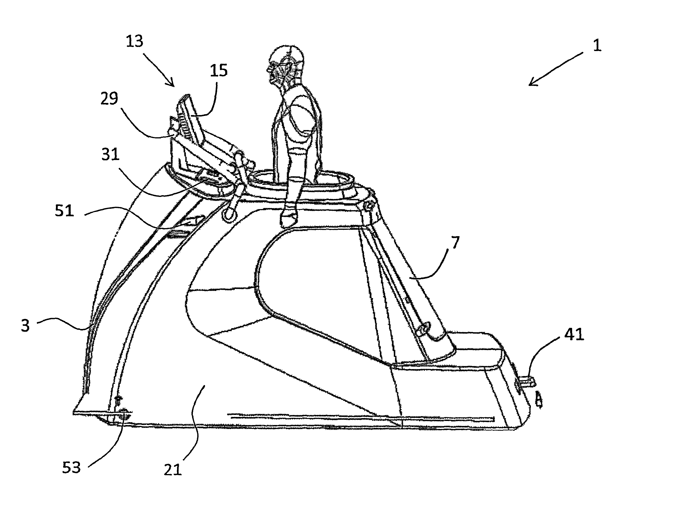
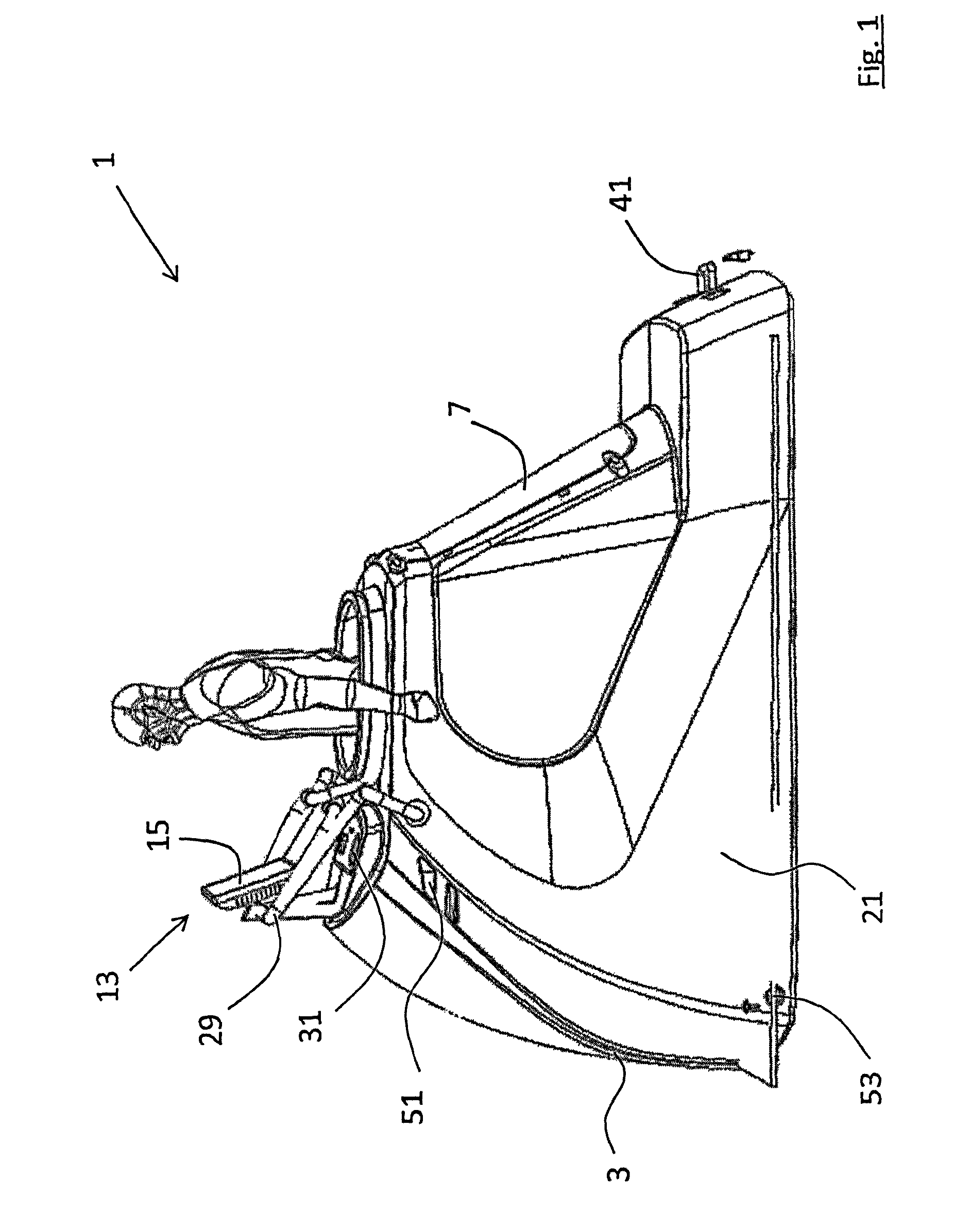
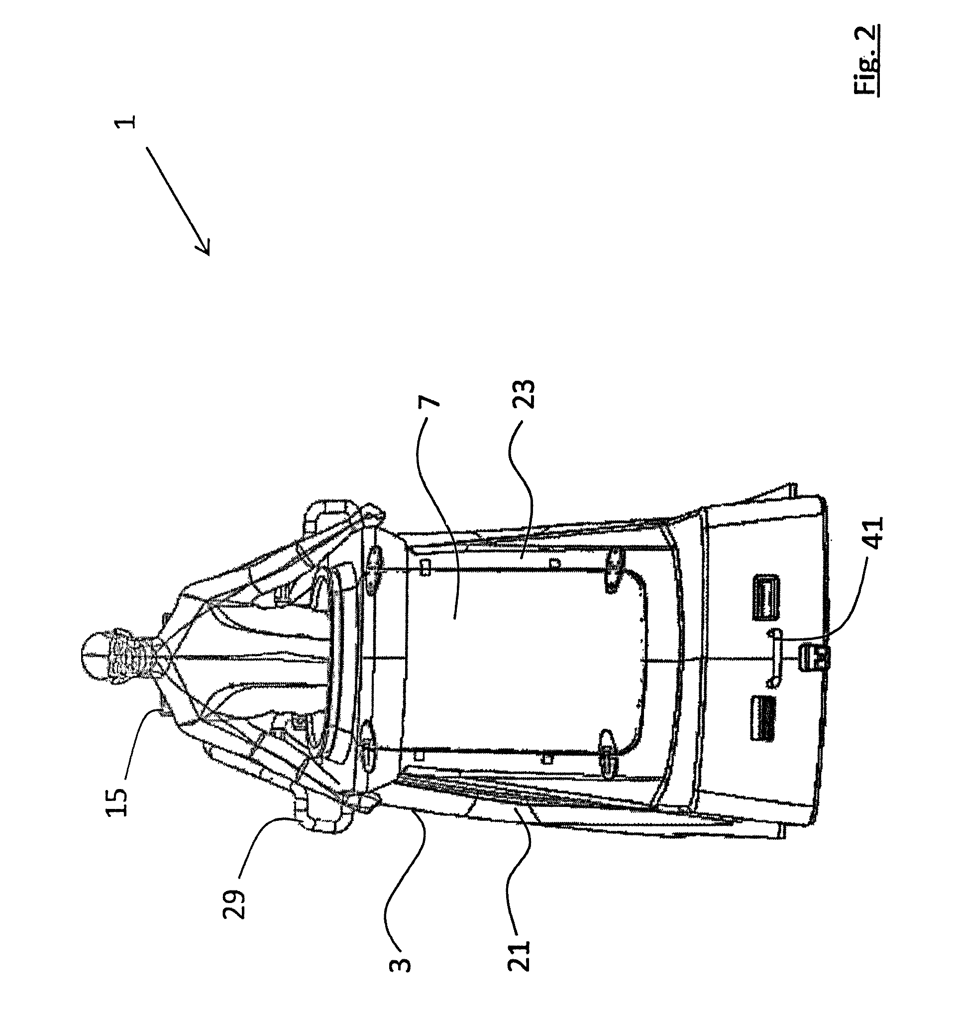
[0029]The invention will now be more clearly understood from the following description of some embodiments thereof given by way of example only with reference to the accompanying drawings, in which:

[0030]FIG. 1 is a perspective view of an exercise device according to the invention;

[0031]FIG. 2 is a rear view of the exercise device shown in FIG. 1;

[0032]FIG. 3 is a left hand side perspective view of the exercise device with a casing panel removed;

[0033]FIG. 4 is a rear perspective view of the exercise device shown in FIG. 3;

[0034]FIG. 5 is a front perspective view of the exercise device shown in FIG. 3;

[0035]FIG. 6 is a side perspective view shown from below of the exercise device shown in FIG. 3;

[0036]FIG. 7 is a top plan view of the exercise device shown in FIG. 3;

[0037]FIG. 8 is front view of the exercise device shown in FIG. 3;

[0038]FIG. 9 is a right hand side view of the exercise device shown in FIG. 3;

[0039]FIG. 10 is rear perspective view of the exercise device shown in FIG. 3...


PUM


Abstract

This invention relates to an exercise device and more particularly to an exercise device of the type that allows the user of the exercise device to exercise with part of their body in a negative pressure environment. These devices are becoming increasingly popular however the known devices are prone to frequent failure. The present invention provides a construction of exercise device that reduces the incidences of failure caused by failure of the electronics panel. The electronics panel being mounted in a separate dedicated enclosure internal the chamber with the negative pressure environment, the interior of the dedicated enclosure is isolated from the negative pressure conditions and atmosphere in the remainder of the chamber. The exercise device will be more reliable and cost effective to run. Furthermore, the construction of the present invention permits easier access to the interior of the casing for maintenance when maintenance is required.

Description

RELATED APPLICATIONS[0001]The subject application is a U.S. National Stage application of International Application No. PCT / EP2012 / 060933, which claims the priority of United Kingdom National Application No.: 1109577.5, filed on 8 Jun. 2011, the contents of which are herein incorporated by reference in its entirety.INTRODUCTION[0002]This invention relates to an exercise device and more particularly to an exercise device of the type that allows the user of the exercise device to exercise with part of their body in a negative pressure environment.[0003]Exercise devices that allow the user of the exercise device to exercise with part of their body in a negative pressure environment have become increasingly popular. It has been found that by exercising with part of their body in a negative pressure environment, for example that part of their body below the torso, the quality and intensity of the workout can be improved significantly. This leads to a reduction in the amount of time requi...

Claims


Application Information

Patent Timeline
Patent Type & Authority Patents(United States)
IPC IPC(8): A63B24/00
CPCA61G10/023A63B21/00181A63B2208/056A63B24/0087A63B71/0619A63B22/00A61H9/005A63B22/0235A63B23/04
Inventor EGAN
Owner EGAN
Learn More