Electricity storage device and hybrid distributed power supply system

a technology of electric storage devices and distributed power supply systems, applied in the direction of greenhouse gas reduction, transportation and packaging, ac network load balancing, etc., can solve problems such as difficult control

Inactive Publication Date: 2014-12-02
MITSUBISHI HEAVY IND LTD
View PDF12 Cites 4 Cited by
  • Summary
  • Abstract
  • Description
  • Claims
  • Application Information

AI Technical Summary

Benefits of technology

[0008]Therefore, the target output value of a hybrid distributed power supply system is determined according to the amount of charge in a storage battery, which causes a disadvantage in that the purpose of protecting the battery cells of the storage battery is given priority over the main purpose of supplying stable electricity by suppressing output fluctuations in the distributed power supply at the upstream side.
[0029]In the present invention, since electricity supply to the system is controlled with priority over the purpose of protecting the storage battery, there is an advantageous effect in that the electrical energy in the storage battery can be effectively utilized within a range that does not cause overcharging or overdischarging of the storage battery.

Problems solved by technology

Therefore, the target output value of a hybrid distributed power supply system is determined according to the amount of charge in a storage battery, which causes a disadvantage in that the purpose of protecting the battery cells of the storage battery is given priority over the main purpose of supplying stable electricity by suppressing output fluctuations in the distributed power supply at the upstream side.
However, such control is difficult in the above-mentioned electricity storage device.

Method used


Image

  • Electricity storage device and hybrid distributed power supply system
  • Electricity storage device and hybrid distributed power supply system
  • Electricity storage device and hybrid distributed power supply system

Examples


Embodiment Construction

[0058]An embodiment of the electricity storage device and the hybrid distributed power supply system according to the present invention will be described below with reference to the drawings.

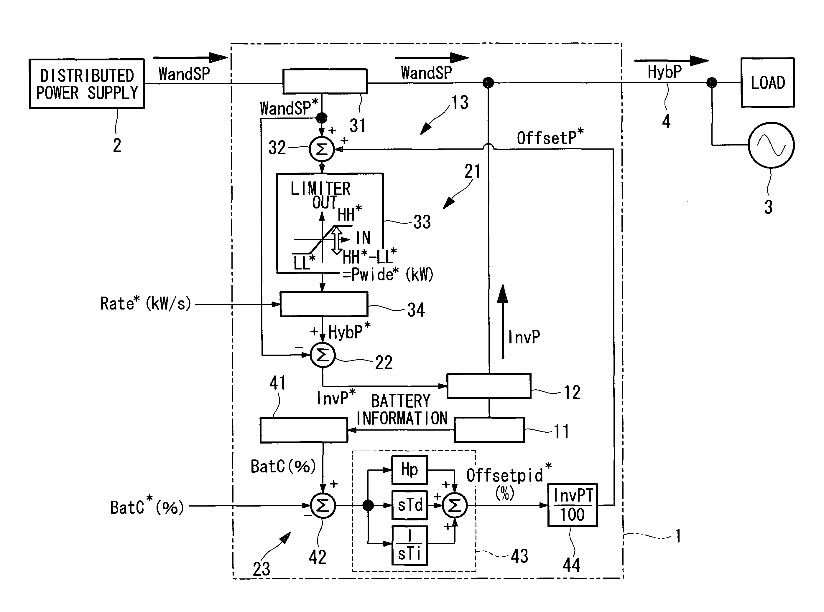
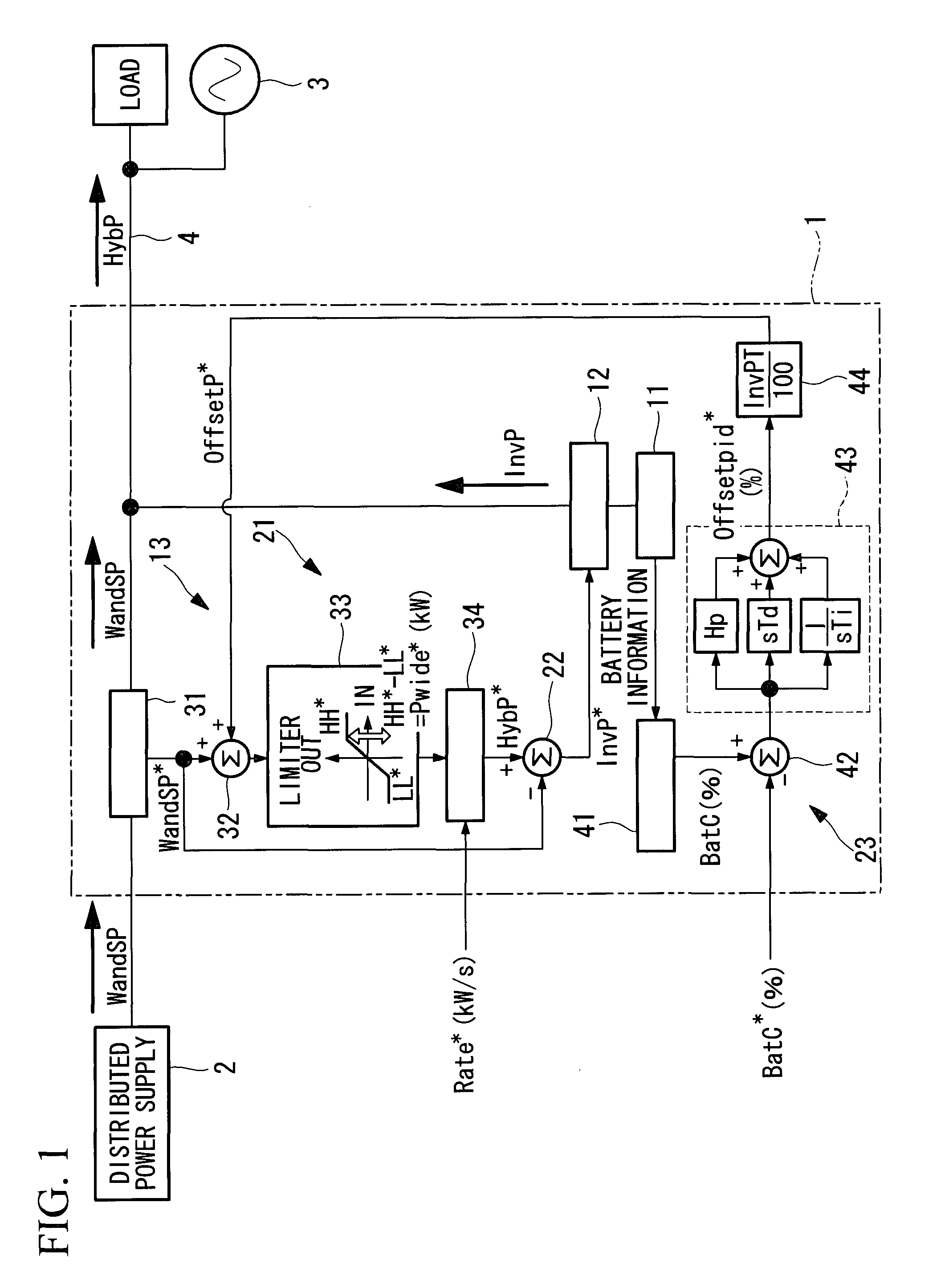
[0059]FIG. 1 is a schematic configuration diagram of a hybrid distributed power supply system that employs an electricity storage device according to an embodiment of the present invention.

[0060]As shown in this diagram, the hybrid distributed power supply system is configured to have a distributed power supply 2 and an electricity storage device 1. The hybrid distributed power supply system is connected to a power supply line 4 for a power supply 3 via a transformer for interconnecting systems (not shown). The power supply 3 herein is, for example, a power supply of an electrical power plant of a power company, a small independent power supply such as a diesel generator on, for example, a remote island, or a private electric generator power supply in a consumer's home.

[0061]In the hybrid distri...


PUM


Abstract

It is an object to effectively output electrical energy of a storage battery to an electrical power system serving as a whole distributed power supply system by effectively utilizing the electrical energy within a charging ratio range that does not cause overcharging or overdischarging of the storage battery. In a hybrid distributed power supply system, the target supply electrical power is set based on the electrical power generation output of the electrical power generator and the charging state of the storage battery, and the target supply electrical power is restricted within a predetermined permissible supply electrical power range when the target supply electrical power deviates from the predetermined permissible supply electrical power range.

Description

TECHNICAL FIELD[0001]The present invention relates to an electricity storage device that is used in a combination with an electrical power generator using natural energy for generating electricity and that supplies the power to an electrical power system so as to reduce the output fluctuation of the electrical power generator.BACKGROUND ART[0002]Electrical power generators utilizing natural energy, such as wind turbine generators or photovoltaic units, have attracted attention because of the global environmental problem. However, since their output is highly influenced by weather conditions, it is difficult to generate electricity in response to demand. In addition, since the system voltage and frequency vary depending on the output fluctuation, the level of adoption of such generators is limited due to restrictions in system operation.[0003]In order to solve these problems, recently, hybrid distributed power supply systems have been developed where electrical power generators utili...

Claims


Application Information

Patent Timeline
Patent Type & Authority Patents(United States)
IPC IPC(8): H02J7/35H02J7/00H02J3/32
CPCH02J7/35H02J3/32H02J7/0073H02J3/383H02J7/0071H02J2300/24H02J3/381Y02E10/56Y02E70/30
Inventor SHIGEMIZU, TETSURONISHIDA, TAKEHIKOKOBAYASHI, KATSUAKITAJIMA, HIDEHIKO
Owner MITSUBISHI HEAVY IND LTD
Why Eureka
Try Eureka