

Imaging lens and imaging apparatus
an imaging lens and lens technology, applied in the field of imaging lenses and imaging apparatuses, can solve the problems of increasing the cost, the angle of view of the lens system is not sufficiently wide, and the requirement for imaging lenses to be mounted on in-vehicle cameras, etc., and achieves the effect of wide angle of view, low cost and small siz
- Summary
- Abstract
- Description
- Claims
- Application Information
AI Technical Summary
Benefits of technology
Problems solved by technology
Method used
Image

Examples
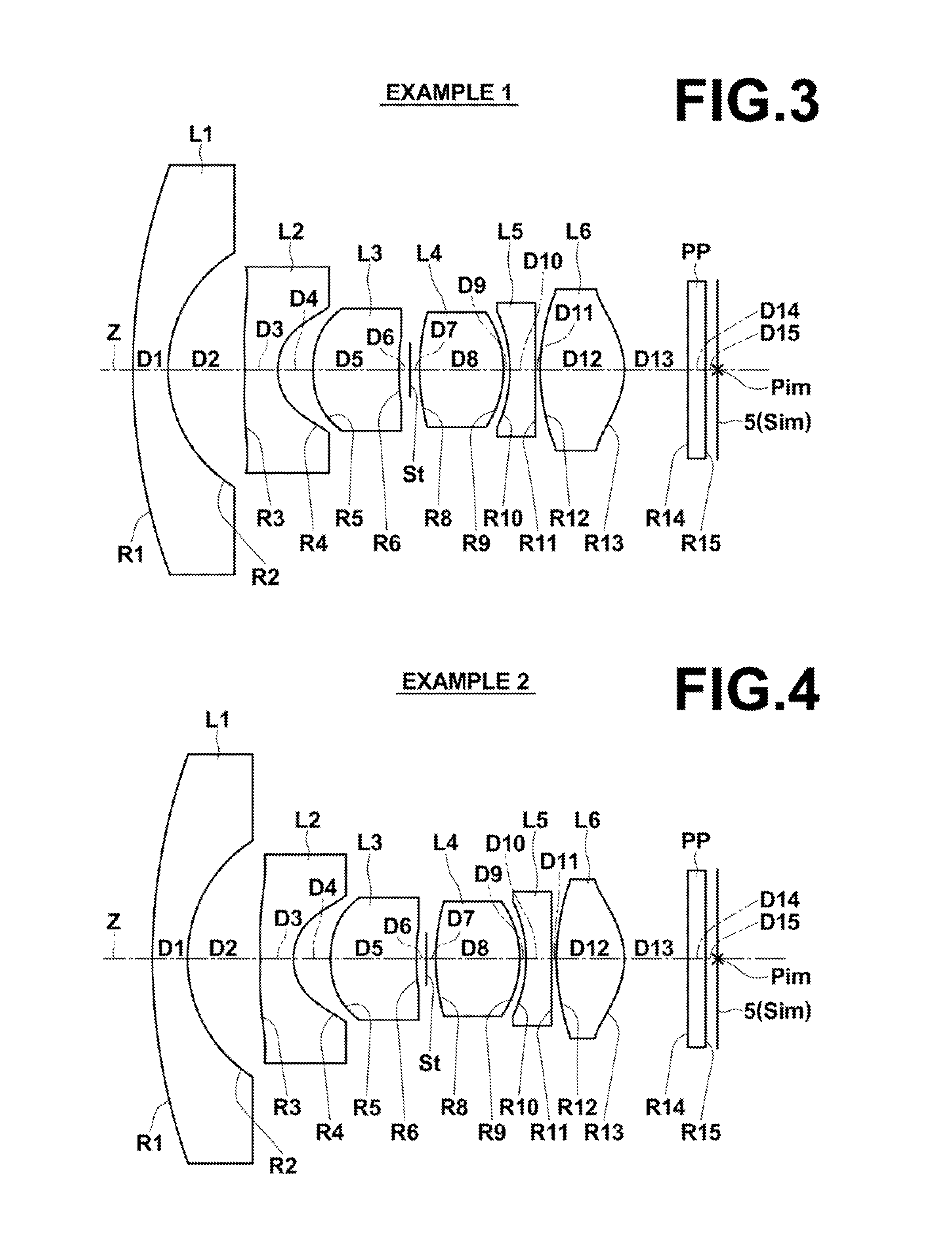
first embodiment
[0094]Further, in the imaging lens an object-side surface of second lens L2 has a shape having negative refractive power at a center, and including a part having positive refractive power in an area between the center and an effective diameter edge, and having negative refractive power at the effective diameter edge (a concave shape facing the object side), and the refractive power at the effective diameter edge is weaker than the refractive power at the center. When the object-side surface of second lens L2 has such a shape, it is possible to reduce the size of the lens system, and to widen an angle of view. At the same time, it is possible to excellently correct curvature of field and distortion. The shape of the object-side surface of second lens L2 will be described later in detail.
[0095]Further, in the imaging lens according to the first embodiment of the present invention, an object-side surface of third lens L3 is convex toward the object side. When the object-side surface o...
second embodiment
[0099]In the imaging lens the material of first lens L1, fourth lens L4 and fifth lens L5 is glass, and the material of second lens L2, third lens L3 and sixth lens L6 is plastic.
[0100]When an imaging lens is used in tough environment conditions, for example, such as use in an in-vehicle camera or a surveillance camera, first lens L1, which is arranged on the most object-side, needs to use a material resistant to a deterioration of a surface by wind and rain and a change in temperature by direct sun light, and resistant to chemicals, such as oils and fats and detergent. In other words, the material needs to be highly water-resistant, weather-resistant, acid-resistant, chemical-resistant, and the like. Further, in some cases, the material needs to be hard and not easily breakable. When the material of first lens L1 is glass, it is possible to satisfy such needs.
[0101]When the material of fourth lens L4 is glass, it is possible to suppress a deterioration of performance caused by a c...
third embodiment
[0106]Further, the imaging lens according to the present invention satisfies the following conditional formula (21):
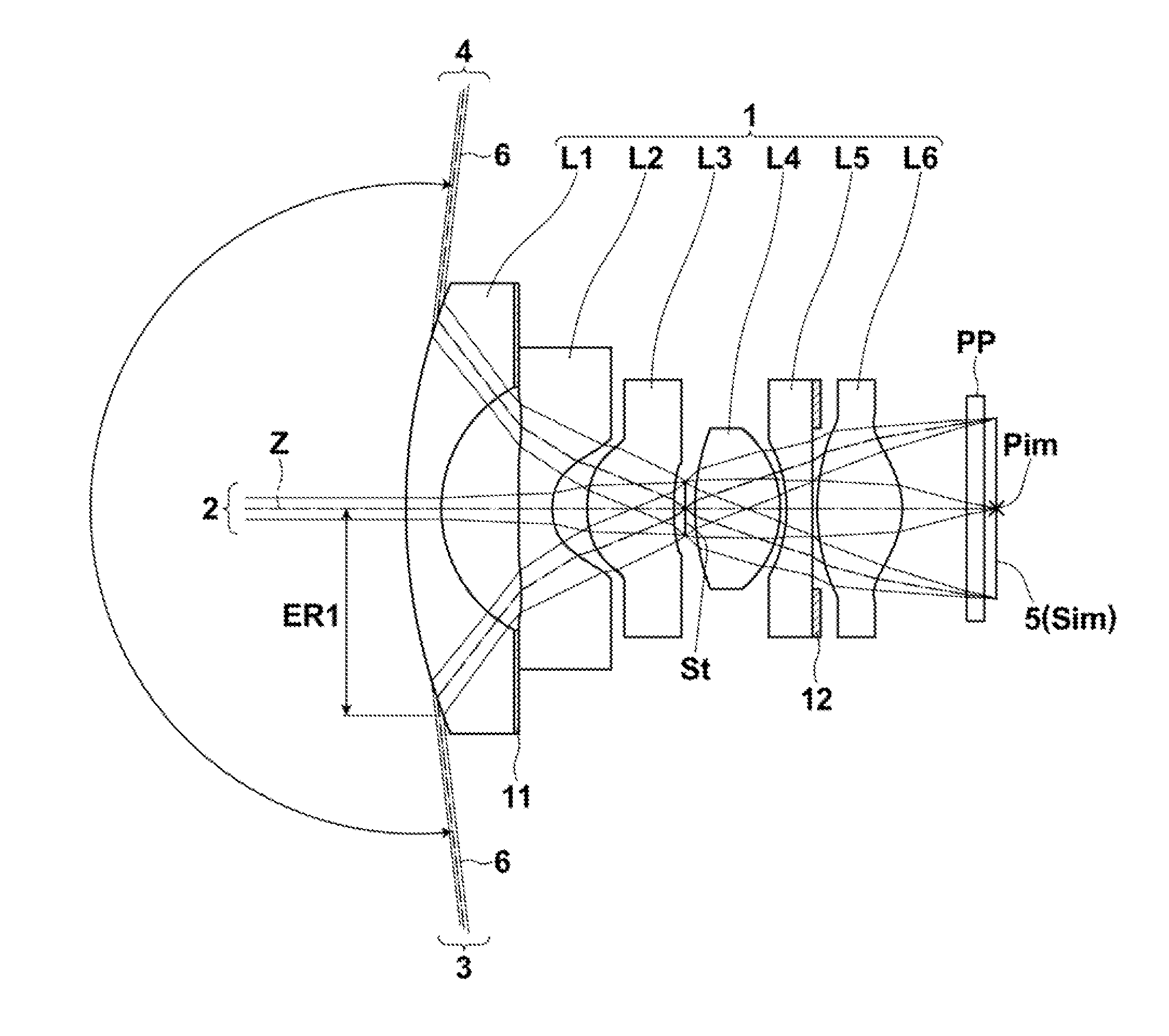
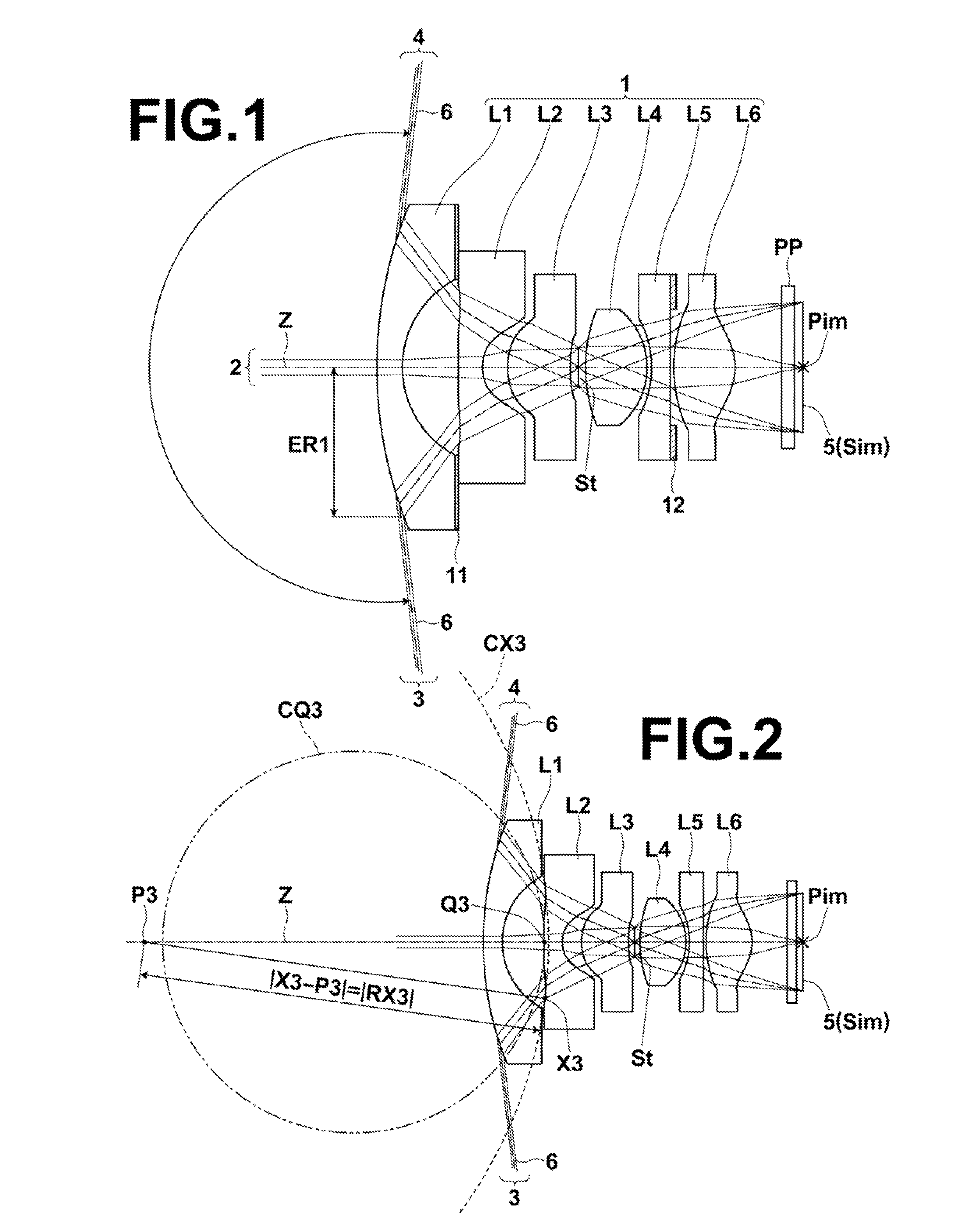
2.5<ER1 / f<7.5 (21), where
[0107]ER1: an effective radius of an object-side surface of first lens L1, and
[0108]f: a focal length of an entire system.
[0109]Here, if a part of an in-vehicle camera exposed to the outside is large, the appearance of the vehicle is damaged. Therefore, a part of the in-vehicle camera exposed to the outside needs to be reduced. When the upper limit of conditional formula (21) is satisfied, it is possible to easily reduce the effective diameter of first lens L1, and to easily suppress the part exposed to the outside so that the part becomes small. When the lower limit of conditional formula (21) is satisfied, it is possible to easily prevent the effective diameter of the object-side surface of first lens L1 from becoming too small. Further, it is possible to easily separate an optical path of central rays and an optical path of off-axial ...
PUM
 Abstract
Description
Claims
Application Information