Semiconductor module and cooler

a technology of semiconductor modules and coolers, applied in the field of coolers, can solve the problems of increasing the cost of the entire cooler, disturbing the cooling performance balance, and cooling a semiconductor module having a plurality of power semiconductor elements, so as to improve the flow velocity of refrigerant, prevent the increase of temperature, and uniform and stable cooling

Active Publication Date: 2014-12-02
FUJI ELECTRIC CO LTD
View PDF27 Cites 13 Cited by
  • Summary
  • Abstract
  • Description
  • Claims
  • Application Information

AI Technical Summary

Benefits of technology

[0011]The present invention was contrived in view of the circumstances described above, and an object thereof is to provide a semiconductor module in which a drift generated in a refrigerant passage can be eliminated so as to improve a refrigerant flow velocity in the vicinity of an introduction port, and in which a semiconductor element can be cooled evenly and stably by preventing the increase in the temperature obtained in the vicinity of the introduction port. The semiconductor module can be prevented from being operated erroneously or being destroyed by heat generated in the semiconductor element.
[0012]Another object of the present invention is to provide a cooler capable of efficiently cooling the semiconductor element.
[0015]According to the semiconductor module of the present invention, the flow velocity of the refrigerant flowing from the first passage to the heat sink can be adjusted by making the cross-sectional area of the refrigerant introduction path smaller than that of the discharge path so that the refrigerant can be guided toward one side surface of the heat sink. Therefore, the semiconductor element disposed on the outer surface of the cooler can be cooled efficiently, whereby the semiconductor element can be operated stably.

Problems solved by technology

Therefore, a major problem is to cool a semiconductor module having a plurality of power semiconductor elements.
However, adopting a new fin material for improving the heat-transfer efficiency of the fin material configuring the cooler can lead to increases in costs of the entire cooler.
Such drift distribution caused in the conventional coolers disturbs the balance of the cooling performance.
Therefore, a uniform and stable cooling performance cannot be accomplished.
Another problem is that only the temperatures of heat generated in the semiconductor elements disposed opposing the refrigerant discharge port increase significantly, reducing the lives of the elements or damaging the elements.
As in the coolers disclosed in Patent Documents 6 and 7 in which the cross-sectional areas of the entrance header parts decrease gradually in a direction in which the entrance header parts extend, their flow rate distributions are improving, but the increase in the temperatures of the sections near the refrigerant introduction ports cannot be prevented.

Method used


Image

  • Semiconductor module and cooler
  • Semiconductor module and cooler
  • Semiconductor module and cooler

Examples


first embodiment

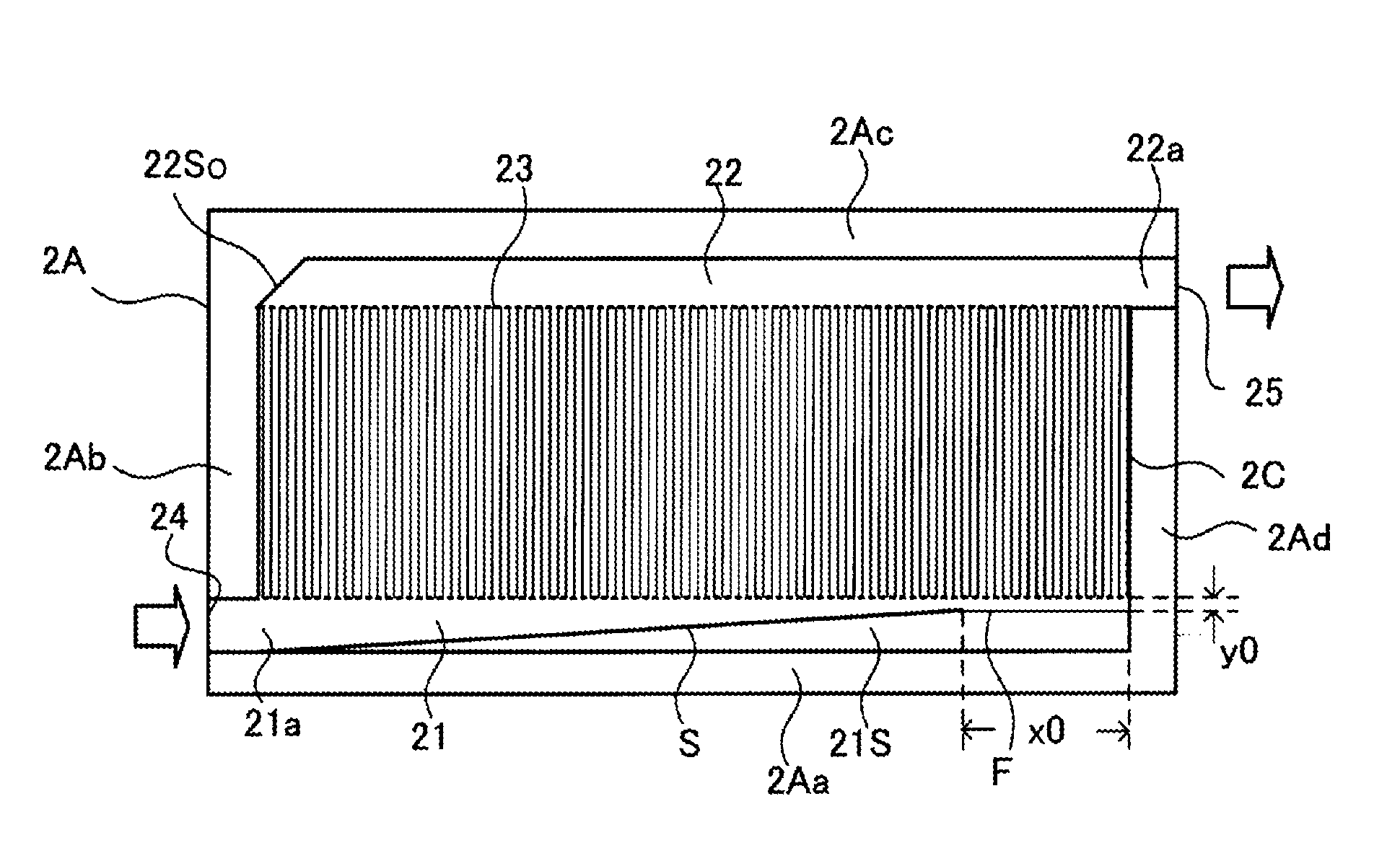
[0122]A first embodiment describes the cooler 2 in which the guide part is disposed in the refrigerant introducing passage 21 so as to adjust a drift generated in the semiconductor module.

[0123]FIGS. 11(A) and 11(B) explain a passage structure of the semiconductor module of the present invention FIG. 11(A) is a plan view of the water jacket of the cooler, and FIG. 11(B) is an explanatory diagram showing different structures of the guide part by type.

[0124]First is described a passage structure in which the refrigerant introducing passage 21 is provided with a guide part 21S. In order to improve the flow velocity distribution of the cooling passage 23, the guide part 21S is configured by an inclined surface S having a predetermined inclination and a flat surface F, as shown in FIG. 11(A).

[0125]The guide part 21S of the present embodiment is formed on the front side wall 2Aa of the water jacket 2A, and the inclined surface S and flat surface F that face a front side surface of the hea...

second embodiment

[0147]FIG. 17 is a plan view showing a water jacket of the conventional semiconductor module, wherein the passage structure of the water jacket is different from that shown in FIG. 9. In the diagrams subsequent to FIG. 17, the positions of the refrigerant introducing passage 21 and the refrigerant discharge passage 22 are switched back and forth from those illustrated in FIGS. 2, 9.

[0148]In this embodiment, the introduction port part 21a and the discharge port part 22a project from the left side wall 2Ab and the right side wall 2Ad of a water jacket 2AI, respectively. A tubular pipe or the like is connected to the water jacket 2AI, and the refrigerant sent from the pump flows into the cooler 2 and then flows out of the discharge port part 22a. As with the refrigerant introducing passage 21 shown in FIG. 9, a side wall of the refrigerant introducing passage 21 of this embodiment is configured by the guide wall S1 that is inclined uniformly in the entire range in which the refrigerant...

third embodiment

[0166]Next is described a method for adjusting the drift by forming a step in a height direction in the refrigerant introducing passage 21 to adjust the drift.

[0167]FIGS. 22(A), 22(B) and 22(C) show a passage structure having steps in a height direction in the semiconductor module shown in FIG. 17. FIG. 22(A) is a plan view showing substantial parts of the water jacket of the cooler, FIG. 22(B) is a cross-sectional diagram taken along the arrow L2-L2 in the vicinity of a refrigerant introduction port, and FIG. 22(C) is an explanatory diagram showing the guide part structures by type.

[0168]In the water jacket 2AI of the present embodiment, an inclined member S21 is superposed along the inclined surface of the guide wall S1 in the refrigerant introducing passage 21 configured by the inclined guide wall S1. The guide part configured by the inclined member S21 forms a side wall that is inclined with respect to the front side surface of the heat sink. The inclined member S21 has two incl...


PUM


Abstract

A semiconductor module and a cooler capable of cooling a semiconductor element efficiently. The semiconductor module supplies a refrigerant to a water jacket configuring the cooler, to cool a circuit element part disposed on an outer surface of a fin base. This semiconductor module has: a fin connected thermally to the circuit element part; a refrigerant introducing passage in the water jacket, which has a guide part that has one surface and another surface inclined to guide the refrigerant toward one side surface of the fin; a refrigerant discharge passage disposed in the water jacket to be parallel to the refrigerant introducing passage, which has a side wall parallel to another side surface of the fin; and a cooling passage formed in a position for communicating the refrigerant introducing passage and the refrigerant discharge passage with each other in the water jacket. The fin is disposed in the cooling passage.

Description

TECHNICAL FIELD[0001]The present invention relates to a cooler for cooling a semiconductor element, and a semiconductor module in which a refrigerant is supplied from the outside to a water jacket configuring the cooler, to cool the semiconductor element disposed on an outer surface of the cooler.BACKGROUND ART[0002]A semiconductor module has been extensively used in a power converter, such as an electrical system of a hybrid vehicle or an electrical vehicle. The semiconductor module configuring an energy-saving controller has a power semiconductor element for controlling a high current.[0003]The heat generated by such a power semiconductor element when controlling a high current tends to increase especially as miniaturization and power boosting of the power semiconductor element advance. Therefore, a major problem is to cool a semiconductor module having a plurality of power semiconductor elements.[0004]A liquid cooling cooler has conventionally been used in such a semiconductor mo...

Claims


Application Information

Patent Timeline
Patent Type & Authority Patents(United States)
IPC IPC(8): H01L25/18H01L23/00H01L23/373H01L25/07H05K7/20G06F1/20H01L23/473F28F3/12
CPCH01L2924/13055H01L2924/01019H01L2224/85447H01L23/3735H01L24/85H01L2224/32225H01L23/473H01L2224/48227H01L2924/01004H01L24/32H01L2924/01078H01L24/48H01L2224/73265H01L2224/85455H01L25/072H01L24/73H01L25/18H01L2924/1305H01L2924/00014H01L2924/00H01L2224/45099H01L2224/45015H01L2924/207
Inventor GOHARA, HIROMICHIICHIMURA, TAKESHIMOROZUMI, AKIRA
Owner FUJI ELECTRIC CO LTD
Why Eureka
Try Eureka