Vehicle with sacrificial underbody structure

a technology of underbody structure and vehicle, which is applied in the direction of protective equipment, transportation and packaging, weapons, etc., can solve the problem of sub-plates being more easily shattered than primary hulls, and achieve the effect of being easy to shatter and easy to shatter

Inactive Publication Date: 2014-12-09
UNITED STATES OF AMERICA THE AS REPRESENTED BY THE SEC OF THE ARMY
View PDF12 Cites 25 Cited by
  • Summary
  • Abstract
  • Description
  • Claims
  • Application Information

AI Technical Summary

Benefits of technology

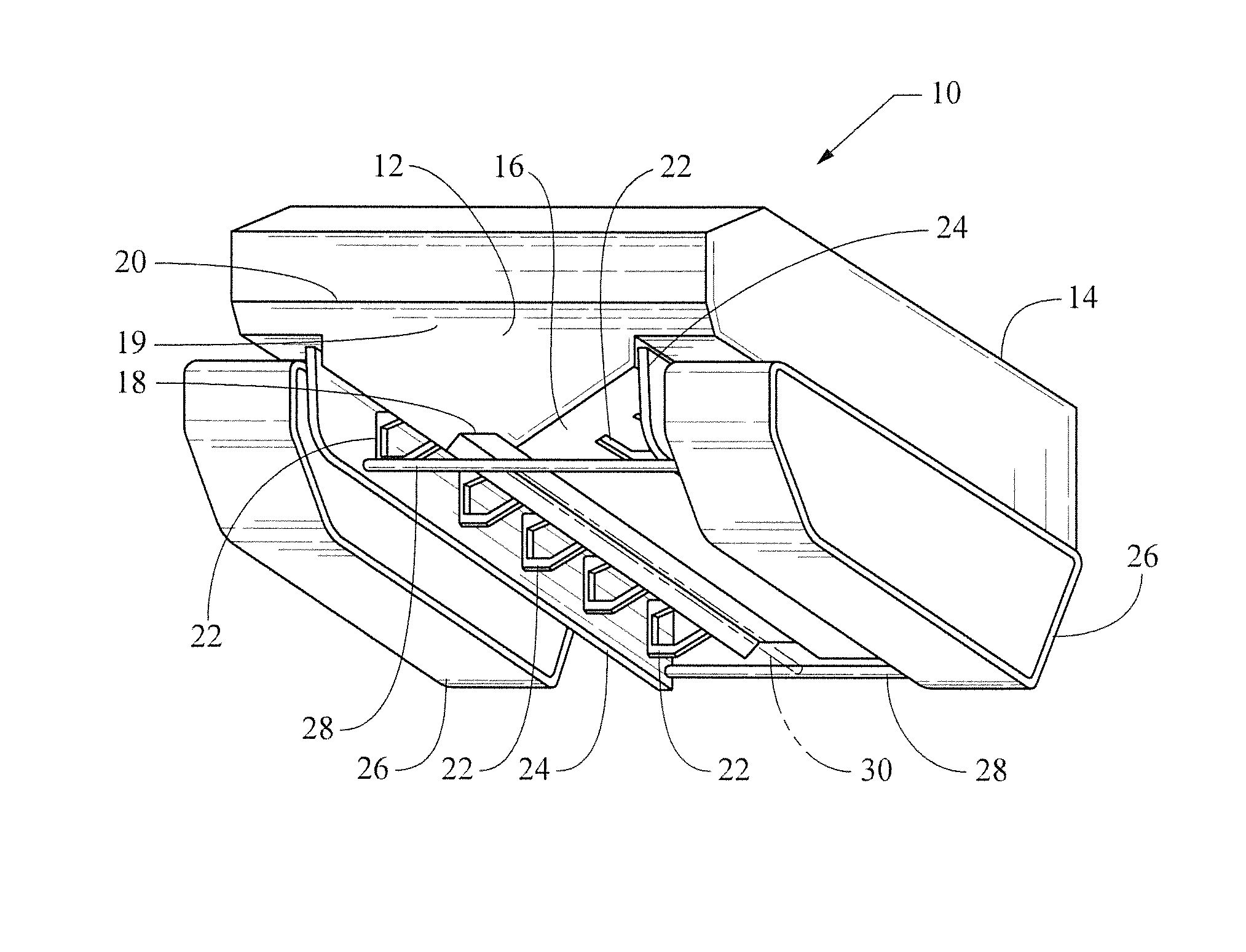
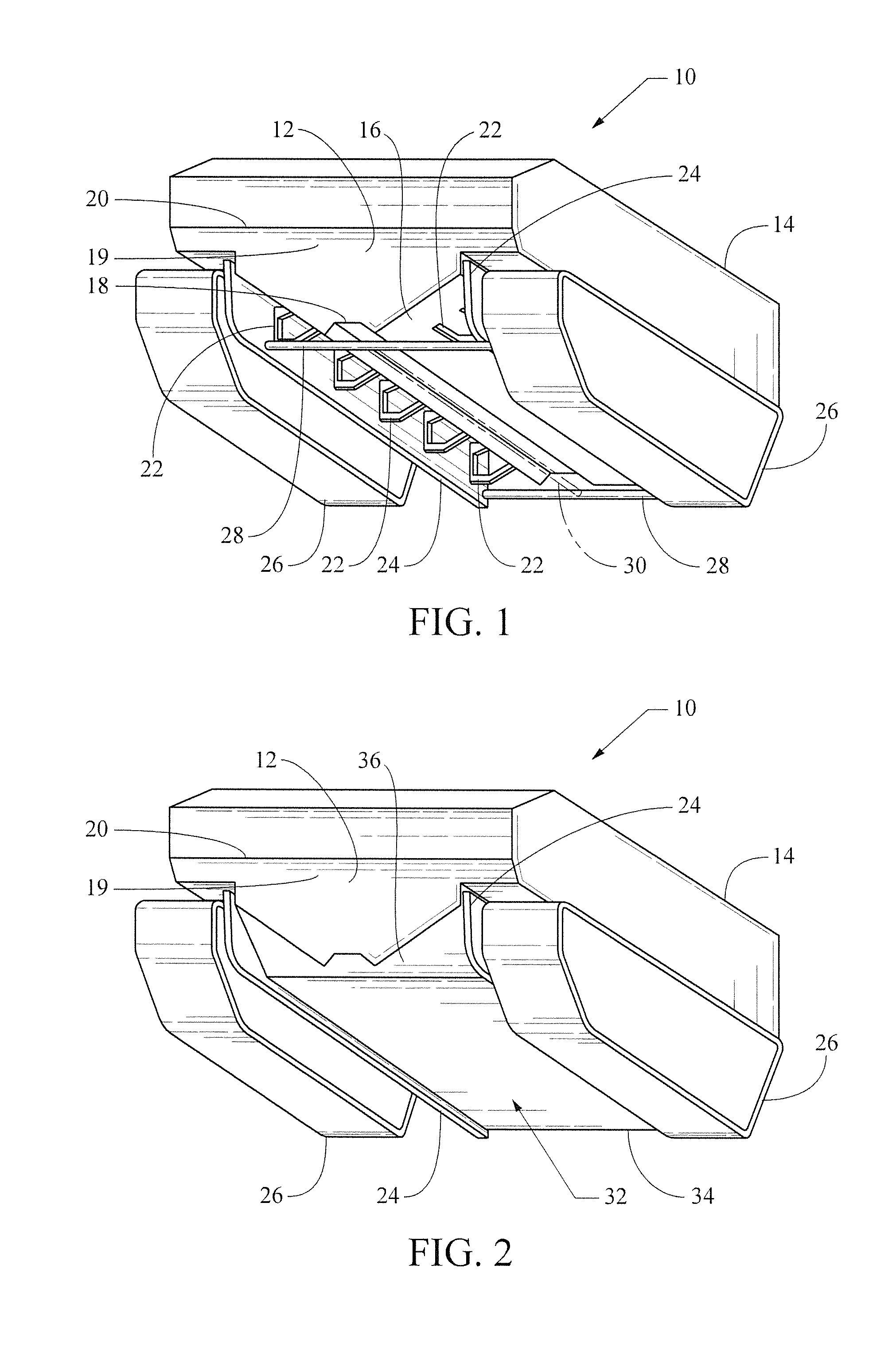
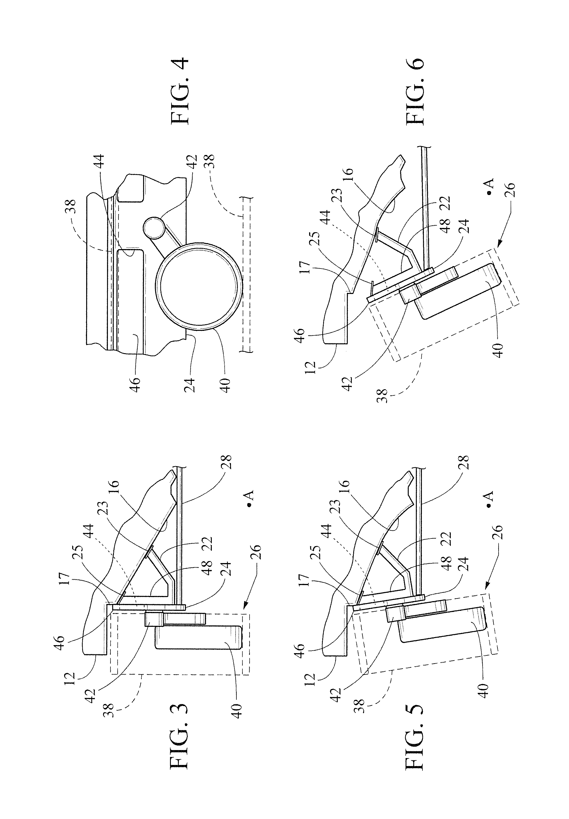
[0006]Our invention is a vehicle having a sacrificial structure for attenuating damage to selected portions of the vehicle and the vehicle's crew due to blast force from an under-vehicle explosion. The sacrificial structure includes elements of the vehicle track and track mounting mechanisms which interconnect and cooperate with elements of a vehicle buoyancy compartment. Our invention is mainly intended for armored vehicles having a typical military vehicle body, though the invention is suitable for other vehicles as well. The vehicle has a primary hull and elongate connector plates disposed along sides of the primary hull to which the vehicle's track assemblies are mounted. The connector plates are affixed to the primary hull by a set of gussets. The connections of the gussets to the primary hull are sacrificial since a sufficiently large blast force detaches the gussets from the primary hull, thereby detaching the connector plates and the track assemblies from the primary hull as well. The detached gussets, connector plates and track assemblies absorb a portion of the blast force that would otherwise affect the primary hull. Cross rods are disposed between the connector plates and affixed thereto. The connection between the cross rod and connector plates can be stronger than the connection between the gussets and the primary hull, whereby the connector plates are tilted outward of the vehicle by a sufficiently large blast force originating under the vehicle. A buoyancy hull beneath the primary hull is attached to the c

Problems solved by technology

Additionally, there are blast relief ports in the connector plates and sacrificial sub plates

Method used


Image

  • Vehicle with sacrificial underbody structure
  • Vehicle with sacrificial underbody structure
  • Vehicle with sacrificial underbody structure

Examples


Embodiment Construction

)

Definitions and Terminology

[0014]The following definitions and terminology are applied as understood by one skilled in the appropriate art.

[0015]The singular forms such as “a,”“an,” and “the” include plural references unless the context clearly indicates otherwise. For example, reference to “a material” includes reference to one or more of such materials, and “an element” includes reference to one or more of such elements.

[0016]As used herein, “substantial” and “about”, when used in reference to a quantity or amount of a material, dimension, characteristic, parameter, and the like, refer to an amount that is sufficient to provide an effect that the material or characteristic was intended to provide as understood by one skilled in the art. The amount of variation generally depends on the specific implementation. Similarly, “substantially free of” or the like refers to the lack of an identified composition, characteristic, or property. Particularly, assemblies that are identified as ...


PUM


Abstract

A vehicle has a sacrificial buoyancy structure for attenuating damage to the vehicle body due to an under-vehicle explosion. The vehicle has a primary hull, connector plates disposed along the primary hull, track assemblies mounted to the connector plates, and gussets attaching the connector plates to the primary hull. The connection of the gussets to the primary hull is sacrificial in that a sufficient amount of explosive force detaches the gussets, connector plates and track assemblies from the primary hull, whereby the gussets, connector plates and track assemblies absorb a portion of the explosive force. The vehicle further has cross rods disposed between the connector plates and affixed thereto. The vehicle also has a sacrificial buoyancy hull beneath the primary hull attached to the cross members wherein the buoyancy hull, connector plates and primary hull form an enclosed buoyancy compartment enabling the vehicle to float on water.

Description

GOVERNMENT INTEREST[0001]The invention described here may be made, used and licensed by and for the U.S. Government for governmental purposes without paying royalty to us.BACKGROUND OF THE INVENTION[0002]1. Field of the Invention[0003]In one respect, the invention relates to the art of designing military land vehicles for amphibious operation and particularly relates to the use of enclosed compartments in the land vehicle hull to provide buoyancy for the vehicle. In another respect, the invention relates to the art of armoring underbodies of vehicles to counter explosions under the vehicle from land mines or like munitions. In still a further respect, the invention relates to the use of sacrificial components of a vehicle that are destroyed or blown off the vehicle by a land mine blast so as to absorb energy from the blast.[0004]2. Background Art[0005]U.S. Pat. No. 5,564,984 to Mirabella et al discloses an enclosed buoyancy compartment on the bottom of the vehicle; the Mirabella veh...

Claims


Application Information

Patent Timeline
IPC IPC(8): F41H7/04B62D55/06
CPCF41H7/042F41H5/013
Inventor CAPOUELLEZ, JAMES A.KHATIB-SHAHIDI, BIJANGREENE, LEO J.
Owner UNITED STATES OF AMERICA THE AS REPRESENTED BY THE SEC OF THE ARMY
Why Eureka
Try Eureka