Method and system unit for stereoscopic x-ray imaging

a stereoscopic x-ray and imaging system technology, applied in the field of stereoscopic x-ray imaging, can solve the problems of not allowing the generation of spatial or 3d impression of different structures of organs, unable to achieve the perception of foreground and background only to a limited degree, and achieves a very short distance between the central beams of x-ray beam sources. , the effect of small structur

Active Publication Date: 2014-12-09
SIEMENS HEALTHCARE GMBH
View PDF4 Cites 15 Cited by
  • Summary
  • Abstract
  • Description
  • Claims
  • Application Information

AI Technical Summary

Benefits of technology

[0026]As a result of the application a minimum of time is lost between the recording of two x-ray images, in other words between the acquisition of two x-ray image datasets, with different projections, because the measurement value is not read directly out from the light-sensitive receivers into the central memory in a time-consuming manner but is read out into the buffer in a time-saving manner. As a result the difference between the two x-ray images from slightly offset projections is minimal in the event of possible movement of the image object, so the stereoscopic image is of high quality even under such difficult recording conditions.
[0027]In one embodiment of the application in method step S6 the measurement values are first read into the buffer or out from the light-sensitive receivers into the buffer and are then read out from the buffer into the central memory. In this embodiment there is no need for a special read-out mechanism from the light-sensitive receiver to the central memory. Instead it is sufficient to have read-out facilities for reading a measurement value out from the respective light-sensitive receiver into the buffer and at the same time read-out facilities for reading a measurement value out from the buffer into the central memory. This allows the x-ray radiation detector used for the method to have a compact and low-cost structure.
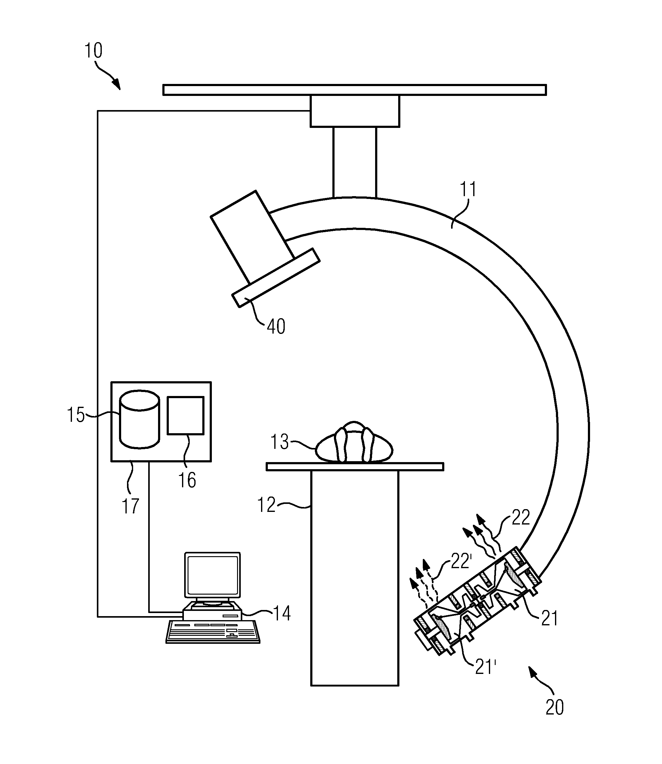
[0032]The x-ray radiation detector allows virtually simultaneous imaging from two angles. This is important for recording images of moving organs such as the heart, aorta or liver or moving objects such as guide wires, catheters or coils. For the identical spatial assignment of a moving object in the stereo image it would be ideal if the two projection images were generated at the same time. However this is not possible in principle due to the one x-ray detector, so the task of the system unit for stereoscopic x-ray imaging is to record the two images as quickly as possible one after the other. This requires a detector technology that supports such timing. Technologies and systems used until now, for example image amplifier / TV tube camera, image amplifier / frame transfer CCD camera, CsI or a-Si-based flat screen detectors, do not allow two recordings to be generated one after the other in the shortest possible time, to document a virtually identical state of movement of the object, e.g. an organ. The application uses detectors, which are produced using CMOS technology (complementary metal oxide semiconductor) or related technologies based on crystalline silicon, and have specific properties, such as fast buffers, also referred to as shadow registers, which make it possible to carry out two separate x-ray recordings with a short interval and to perform the read-out process, which is typically relatively time-consuming, in a less time-critical phase. This approach is suitable for stereoscopic imaging involving moving objects.
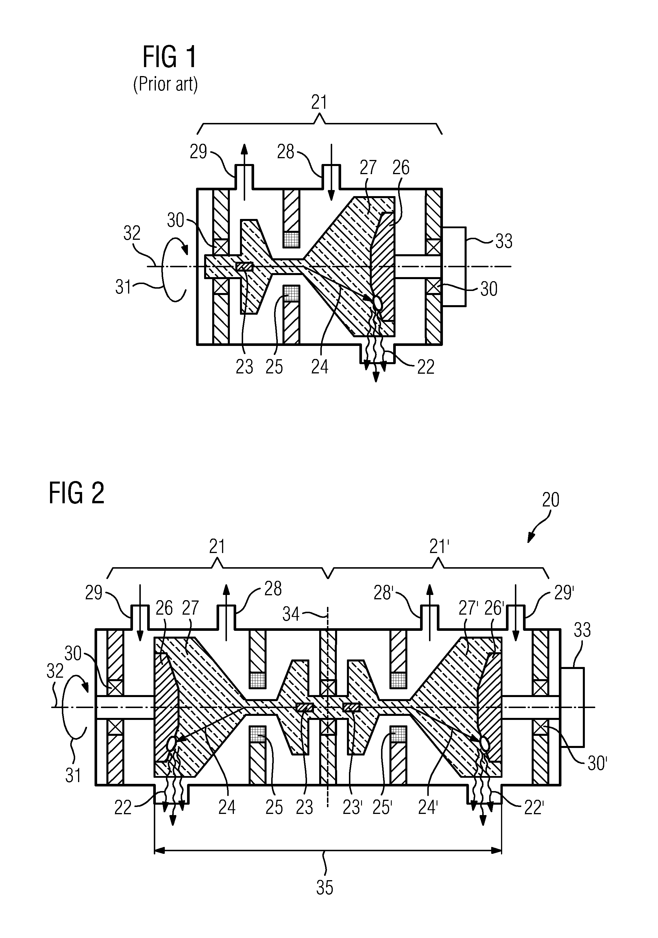
[0033]It is important for the stereoscopic x-ray tube that the two x-ray beam sources are disposed a short distance from one another and can generate radiation, which is registered on the x-ray detector, one after the other. With minimum possible distances of approx. 6.5 cm to 10 cm it is to dispose the x-ray beam sources together in a housing. Alternatively for greater distances two separate emitters can also be disposed next to one another. Emitters with a grounded anode would be advantageous here as they can be designed to be smaller in structure.
[0034]In one embodiment of the application the x-ray beam sources each comprise an anode plate / cathode pair, which are disposed along a center line, and the anode plate / cathode pairs are disposed with mirror symmetry with a mirror plane perpendicular to the center line. X-ray beam sources, in which an anode plate and cathode are disposed on an center line, are known from the prior art. In this embodiment of the application it is now proposed that two such x-ray beam sources should be disposed on an center line and the geometric sequence of anode plate and cathode should be such that the position of the x-ray beam sources has mirror symmetry in respect of a perpendicular of the center line. In principle this allows sequences in which the two cathodes are disposed between the two anode plates or in which the two anode plates are disposed between the two cathodes. The latter instance has the feature that the two anode plates can be constructed closer together, with the result that the distance between the central beams of the x-ray beam sources is very short.

Problems solved by technology

Displaying an organ from two projection directions using two detector planes, in other words a biplane system, however does not permit the generation of a spatial or 3D impression of different structures of an organ, for example the intersection of vessels or position of an aneurism, or other objects.
Any perception of foreground and background is only possible to a limited degree.
If the differences between the two images are not only due to the different projection settings, but are also due to movement, an identical spatial assignment of the object in the stereo image is not possible.
Simultaneous recording of the two images is not possible in principle due to the one x-ray detector, so there is always a certain time interval between the recording of the two images.
This means that there is deterioration in image quality for moving objects.

Method used


Image

  • Method and system unit for stereoscopic x-ray imaging
  • Method and system unit for stereoscopic x-ray imaging
  • Method and system unit for stereoscopic x-ray imaging

Examples


Embodiment Construction

[0047]FIG. 1 shows an embodiment of an x-ray beam source 21, which comprises an x-ray tube for generating x-ray beams 22 according to the prior art. More specifically it comprises a cathode 23 and an anode plate 26, which are disposed in an evacuated glass body 27. The electrons 24 emitted by the cathode 23 are accelerated by a high voltage and, in some instances after their flight path has been controlled by deflection coils 25, strike the anode plate 26, where they are slowed down and generate the characteristic x-ray radiation, braking radiation and Lilienfeld radiation. The x-ray beam source 21 is embodied as a so-called rotating envelope tube. This means that the glass body 27, which is guided in bearings 30, the cathode 23 and the anode plate 26 are shaped with rotational symmetry in relation to an axis of rotation 32 and can execute a rotational movement 31 with the aid of a symbolically represented motor 33. To cool the anode plate, which becomes hot due to the electron bomb...


PUM


Abstract

A method for stereoscopic x-ray imaging by a stereoscopic x-ray tube and by an x-ray radiation detector is provided. The x-ray radiation detector has a buffer. The stereoscopic x-ray tube has two x-ray beam sources disposed a short distance from one another. 2D image datasets are acquired at relatively short intervals one after the other, which have good quality.

Description

CROSS REFERENCE TO RELATED APPLICATIONS[0001]This application claims priority of German application No. 10 2011 081 550.3 filed Aug. 25, 2011, which is incorporated by reference herein in its entirety.FIELD OF INVENTION[0002]The present application relates to a method for stereoscopic x-ray imaging. The present application also relates to a corresponding system unit for stereoscopic x-ray imaging.BACKGROUND OF INVENTION[0003]X-ray systems are frequently used for imaging for the purposes of diagnostic examination and for interventions, for example in the areas of cardiology, radiology and surgery. These x-ray systems generally comprise a C-arm, on which an x-ray tube and x-ray detector are disposed opposite one another, a patient couch and a system control and display unit. Systems with two planes, i.e. with two C-arms, are also used in interventional radiology.[0004]Monoplane systems, i.e. x-ray systems with one tube and one detector, are used both for diagnostic purposes, e.g. duri...

Claims


Application Information

Patent Timeline
Patent Type & Authority Patents(United States)
IPC IPC(8): A61B6/02H01J35/30A61B6/00
CPCH01J35/305A61B6/022A61B6/4441A61B6/545A61B6/4007A61B6/504A61B6/50A61B6/486G01N2223/414A61B6/4208A61B6/542
Inventor BERNHARDT, PHILIPPSPAHN, MARTIN
Owner SIEMENS HEALTHCARE GMBH
Why Eureka
Try Eureka