Transmitter and method for RF power amplifier having a bandwidth controlled, detroughed envelope tracking signal

a technology of rf power amplifier and envelope tracking signal, which is applied in the field of rf communication systems, can solve the problems of rf transmitters in violation of their regulatory spectral masks, linear rf power amplifiers invariably failing to meet, and nonlinearities,

Inactive Publication Date: 2014-12-09
CRESTCOM INC
View PDF12 Cites 95 Cited by
  • Summary
  • Abstract
  • Description
  • Claims
  • Application Information

AI Technical Summary

Problems solved by technology

While perfect linearity is a goal for any linear RF power amplifier, all linear RF power amplifiers invariably fail to meet it.
The degree to which the goal of perfect linearity is missed leads to unwanted intermodulation, nonlinearities, and spectral regrowth.
Accordingly, unless the spectral regrowth that results from any nonlinearity in the amplification process is held to a very low level, the RF transmitter may be in violation of its regulatory spectral mask.
An amplifier that has low PAE wastes power, which is undesirable in any transmitter, but particularly undesirable in battery-powered transmitters because it necessitates the use of undesirably large batteries and / or undesirably frequent recharges.
When such techniques are combined with conventional digital predistortion techniques, the RF power amplifiers may also achieve modest amounts of linearity.
But prolonged durations greater than a complete cycle of the RF waveform with VDSGS−VT lead to significant nonlinearity in the operation of the RF power amplifier and to spectral mask violations.
Conventional digital predistortion techniques are unable to adequately compensate for such gain fluctuations.
Providing infinite predistortion gain to compensate for gain collapse is not achievable using realistic components.
Moreover, conventional digital predistortion techniques are powerless to compensate for the resulting significant nonlinearity and spectral regrowth that occur.
Unfortunately, the conventional detroughing techniques merely tend to replace greater amounts of nonlinearity resulting from one characteristic of RF power amplifier operation with lesser amounts of nonlinearity resulting from another characteristic of RF power amplifier operation.
As a result, conventional RF power amplifiers which employ ET and waveform shaping tend to achieve only modest linearity with significant PAE improvements.

Method used


Image

  • Transmitter and method for RF power amplifier having a bandwidth controlled, detroughed envelope tracking signal
  • Transmitter and method for RF power amplifier having a bandwidth controlled, detroughed envelope tracking signal
  • Transmitter and method for RF power amplifier having a bandwidth controlled, detroughed envelope tracking signal

Examples


Embodiment Construction

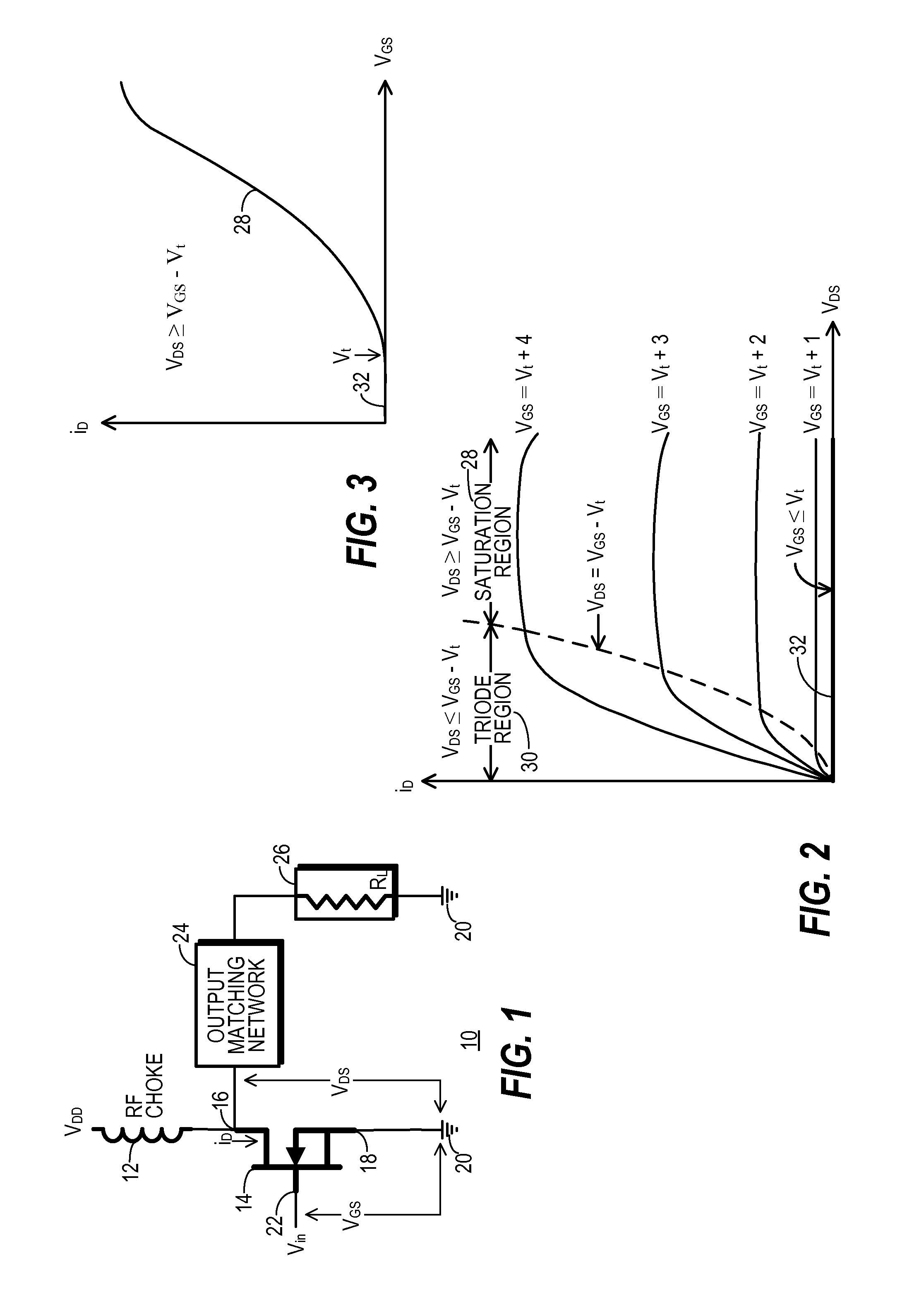
[0028]FIG. 1 shows a simplified block diagram of a generic form of an RF power amplifier 10. A biasing signal VDD is applied through an RF choke inductor 12 to an output of a core amplifying device 14, represented in FIG. 1 using a field effect transistor (FET) symbol. The biasing signal is shown as being applied to a drain 16 of device 14. Those skilled in the art will appreciate that a wide variety of FET amplifying devices, including MOS, CMOS, LDMOS, and the like may be used as amplifying device 14 and that other types of transistor and tube forms of amplifying devices 14 may also be used. Moreover, while FIG. 1 shows only a single amplifying device 14 for simplicity, RF power amplifier 10 may use multiple active devices coupled together to serve in the role of amplifying device 14. Examples of such multiple-device structures include a push-pull configuration commonly used for class AB operation and a stack commonly used with CMOS amplifying devices.

[0029]A source 18 of amplifyi...


PUM


Abstract

A transmitter (70) generates a time-varying, detroughed, biasing signal (154) for an RF power amplifier (10) so that the RF power amplifier (10) is biased in accordance with an envelope tracking scheme. A trough-filling section (94) is responsive to an envelope tracking signal (86), which in turn is responsive to a magnitude signal (90) extracted from a complex baseband communication signal (76). The trough-filing section (94) includes a limiting stage (108) that forms a raw troughing signal (110) which expands the bandwidth of the envelope tracking signal (86). A filtering stage (116) reduces the bandwidth of the raw troughing signal (110) to form a trough-filling signal (122) that is combined back into the envelope tracking signal (86) using a linear process that maintains the bandwidth of the envelope tracking signal (86).

Description

TECHNICAL FIELD OF THE INVENTION[0001]The present invention relates generally to the field of radio-frequency (RF) communication systems. Specifically, the present invention relates to RF transmitters that generate and use RF power amplifier biasing signals which track the RF communication signal envelope to improve power added efficiency and which employ envelope waveform shaping to prevent gain collapse in the RF power amplifier.BACKGROUND OF THE INVENTION[0002]An RF power amplifier provides the final stage of amplification for a communication signal that has been modulated and converted into an RF signal. Often that RF signal exhibits frequencies in a predetermined frequency band that is licensed by a regulatory agency for a particular use. The RF power amplifier boosts the power of this RF communication signal to a level sufficient so that the signal, when it propagates to an antenna, will be broadcast in such a manner that it will meet the communication goals of the RF transmit...

Claims


Application Information

Patent Timeline
Patent Type & Authority Patents(United States)
IPC IPC(8): H04B1/04H04L25/08H01Q11/12
CPCH04B1/0475H04L25/08H04L27/368H03F1/0227H03F1/3247H03F2200/102H03F2200/451
Inventor MCCALLISTER, RONALD, DUANE
Owner CRESTCOM INC
Why Eureka
Try Eureka