
Lightweight steel door for vehicle and method for manufacturing the same

a technology for vehicle doors and steel doors, applied in the direction of doors, roofs, transportation and packaging, etc., can solve the problems of increasing the cost of aluminum doors, increasing the cost of steel doors, and increasing the complexity of manufacturing, so as to improve the resistance to side intrusion and strength and thickness. , the effect of improving the resistan

Active Publication Date: 2014-12-16
ARCELORMITTAL INVESTIGACION Y DESARROLLO SL
View PDF10 Cites 11 Cited by
  • Summary
  • Abstract
  • Description
  • Claims
  • Application Information

AI Technical Summary

Benefits of technology

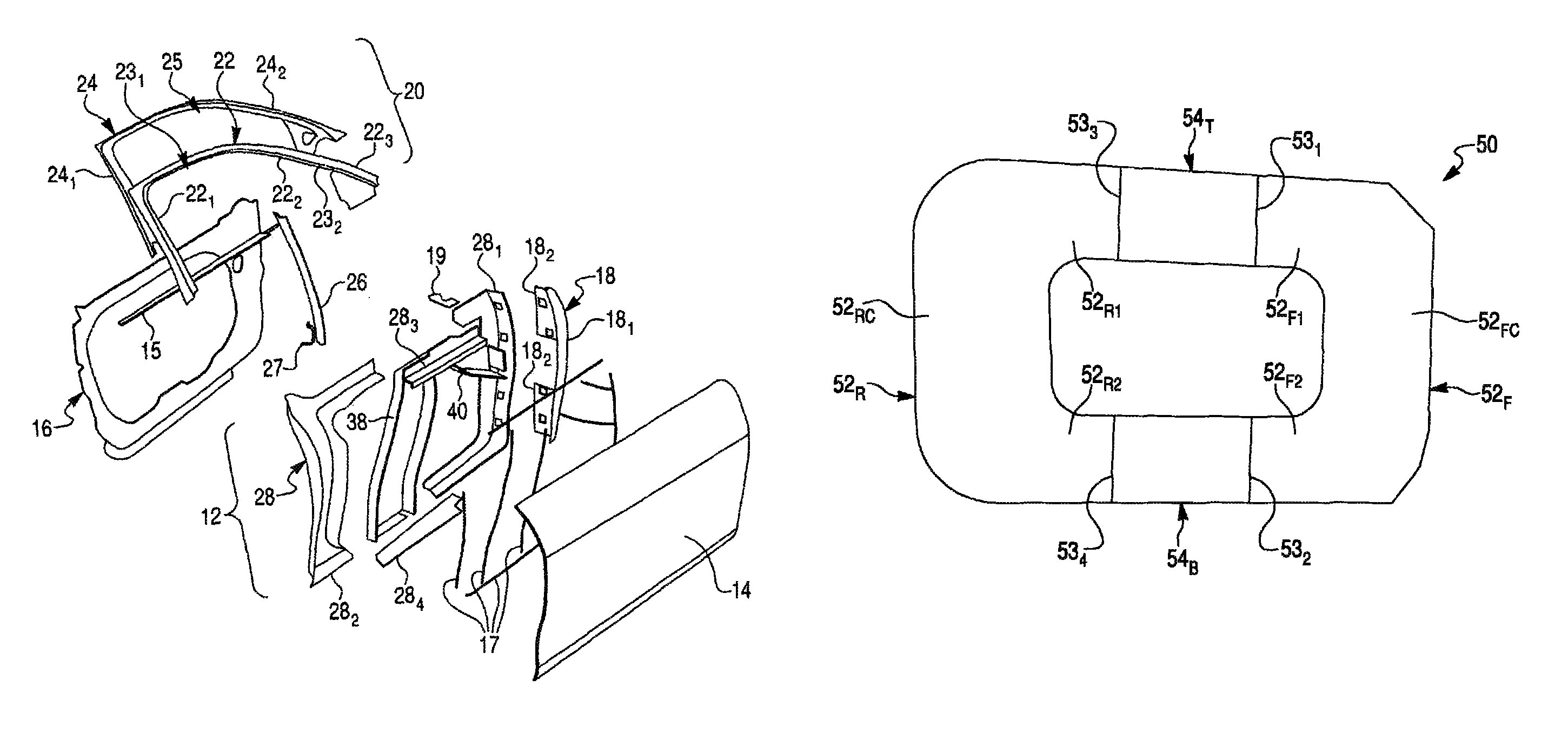
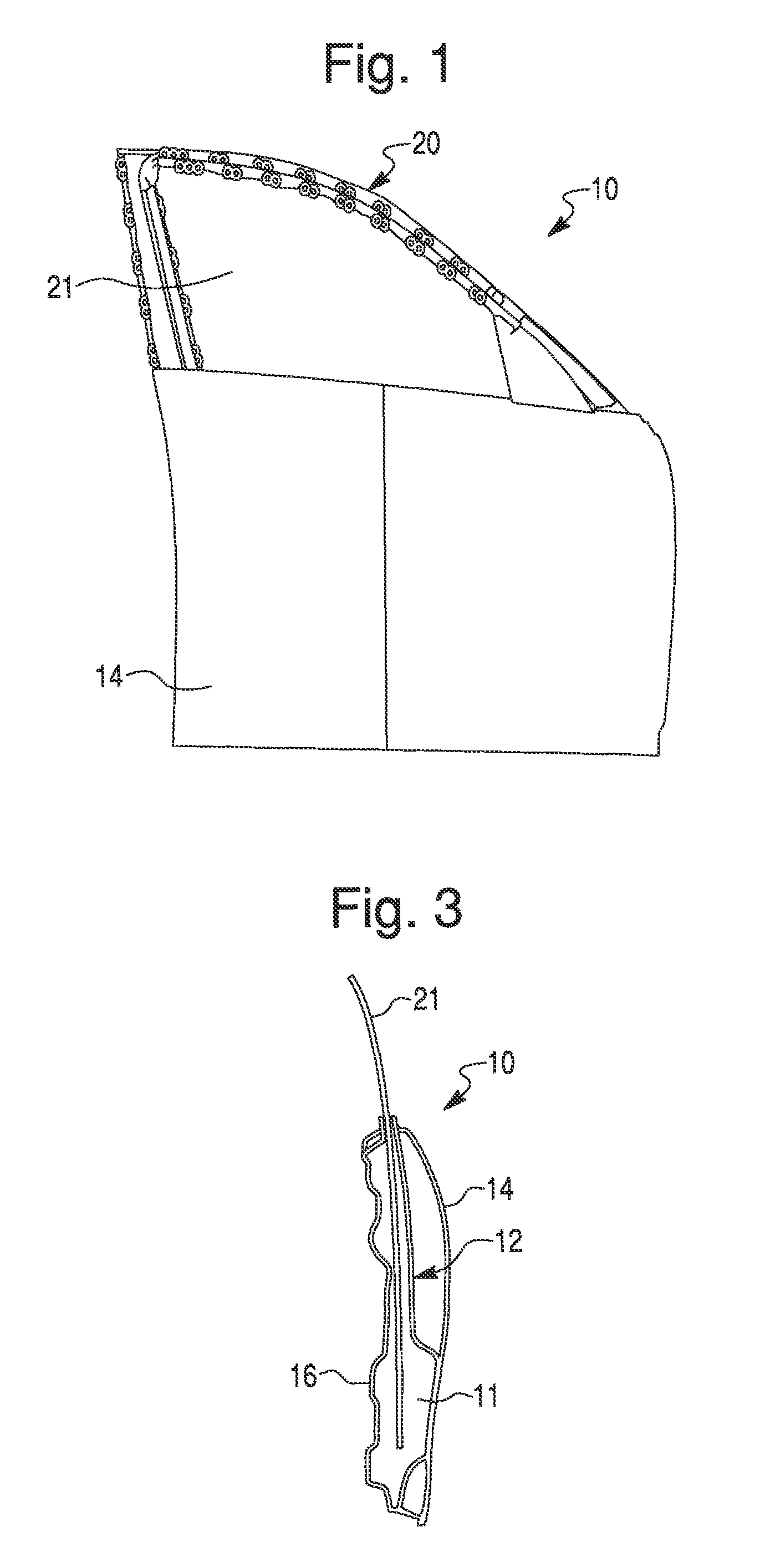
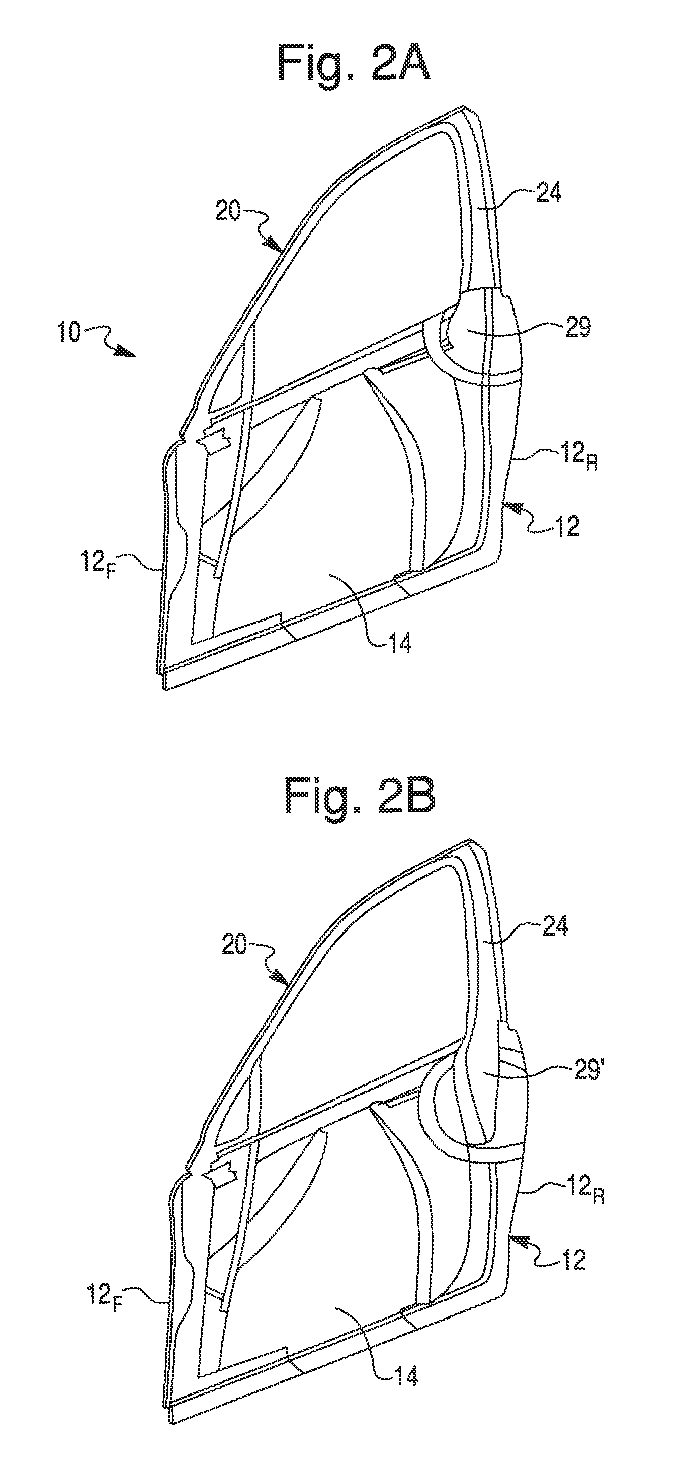
The present invention provides a method for manufacturing an inner panel of a vehicle door assembly. The method involves using front and rear flat U-shaped steel sheets made of a first steel material and top and bottom flat steel sheets made of a second steel material. The U-shaped steel sheets are connected to the top and bottom sheets to form a flat door perimeter frame blank, which is then stamped into a perimeter frame portion of the inner panel. The front and rear U-shaped sheets are made of a different steel material from the top and bottom sheets, and the frame portion comprises opposite front and rear U-shaped side frame members non-detachably attached to each other by upper and lower intermediate frame members so as to form the continuous perimeter. This design improves resistance to side intrusion.

Problems solved by technology

However, conventional steel door designs are relatively heavy in comparison to the mass of newly designed aluminum doors.
The aluminum doors, although lighter than conventional steel doors, are however costlier than steel doors and more complex, difficult and expensive to manufacture.
Therefore, vehicle doors made of steel are susceptible to improvements that may enhance their performance, cost and weight.

Method used


Image

  • Lightweight steel door for vehicle and method for manufacturing the same
  • Lightweight steel door for vehicle and method for manufacturing the same
  • Lightweight steel door for vehicle and method for manufacturing the same

Examples


Embodiment Construction

)

[0030]Reference will now be made in detail to exemplary embodiments and methods of the invention as illustrated in the accompanying drawings, in which like reference characters designate like or corresponding parts throughout the drawings. It should be noted, however, that the invention in its broader aspects is not limited to the specific details, representative devices and methods, and illustrative examples shown and described in connection with the exemplary embodiments and methods.

[0031]This description of exemplary embodiments is intended to be read in connection with the accompanying drawings, which are to be considered part of the entire written description. In the description, relative terms such as “horizontal,”“vertical,”“front,”“rear,”“upper”, “lower”, “top” and “bottom” as well as derivatives thereof (e.g., “horizontally,”“downwardly,”“upwardly,” etc.) should be construed to refer to the orientation as then described or as shown in the drawing figure under discussion an...


PUM

PropertyMeasurementUnit
thicknessaaaaaaaaaa
thicknessaaaaaaaaaa
thicknessesaaaaaaaaaa

Abstract

A vehicle door assembly comprises an inner panel integrally formed by upper and lower horizontal beams interconnected by front and rear upright beams, and an outer panel bonded to the inner panel. The frame portion comprises opposite front and rear U-shaped side frame members non-detachably attached to each other by upper and lower intermediate frame members so as to form a continuous perimeter. The side frame members are made of a first steel material and the intermediate frame members made of a second steel material, which is different from the first steel material. A method for manufacturing the inner panel comprises the steps: providing U-shaped sheets of the first steel material, providing top and bottom sheets of the second steel material, non-detachably connecting the U-shaped sheets to the top and bottom sheets so as to form a blank, and stamping the blank into the frame portion.

Description

CROSS-REFERENCE TO RELATED APPLICATION[0001]This Application claims the benefit under 35 U.S.C. 119(e) of U.S. Provisional Application Ser. No. 61 / 541,568 filed Sep. 30, 2011 by Schurter et al., which is hereby incorporated herein by reference in its entirety and to which priority is claimed.FIELD OF THE INVENTION[0002]The present invention relates to vehicle door assemblies and methods for manufacturing thereof in general and, more particularly, to a lightweight vehicle door assembly and method for manufacturing the same using components made of various interconnected high strength steel grades.BACKGROUND OF THE INVENTION[0003]Conventionally, vehicle doors comprise a supportive inner panel made of steel material. An outer panel is attached to the inner panel. The conventional inner panel is deep-drawn from mild steel. A beltline beam beneath the window is welded to the inner panel and can be placed either inwardly of or outwardly of the window. Typically, the vehicle doors include ...

Claims


Application Information

Patent Timeline
Patent Type & Authority Patents(United States)
IPC IPC(8): B60J5/04B60J5/00
CPCB60J5/0483B60J5/0443B60J5/0415B60J5/043B60J5/0429B60J5/0463B60J5/0412B21K7/12B60J5/048Y10T29/49622
Inventor SCHURTER, PAULLIM, TIMOTHYDOLAN, PAULSHARIFI, HAMED
Owner ARCELORMITTAL INVESTIGACION Y DESARROLLO SL
Learn More