
Microfluidic device for generating neural cells to simulate post-stroke conditions

a microfluidic device and post-stroke technology, applied in the direction of fluorescence/phosphorescence, apoptosis detection, instruments, etc., can solve the problem of extremely limited treatment options for ischemic strok

Inactive Publication Date: 2014-12-16
UNIV OF SOUTH FLORIDA +1
View PDF6 Cites 1 Cited by
  • Summary
  • Abstract
  • Description
  • Claims
  • Application Information

AI Technical Summary

Benefits of technology

The device provides an accurate in vitro model for ischemic stroke, facilitating the understanding of cellular communication and enabling the screening of therapeutic interventions, which can help in preventing the expansion of the stroke lesion and improving treatment options.

Problems solved by technology

Treatments for ischemic stroke are extremely limited, in part because of the lack of adequate in vitro models for ischemic stroke.

Method used


Image

  • Microfluidic device for generating neural cells to simulate post-stroke conditions
  • Microfluidic device for generating neural cells to simulate post-stroke conditions
  • Microfluidic device for generating neural cells to simulate post-stroke conditions

Examples


examples

I. Fabrication of a Microfluidic Cell Culture Device

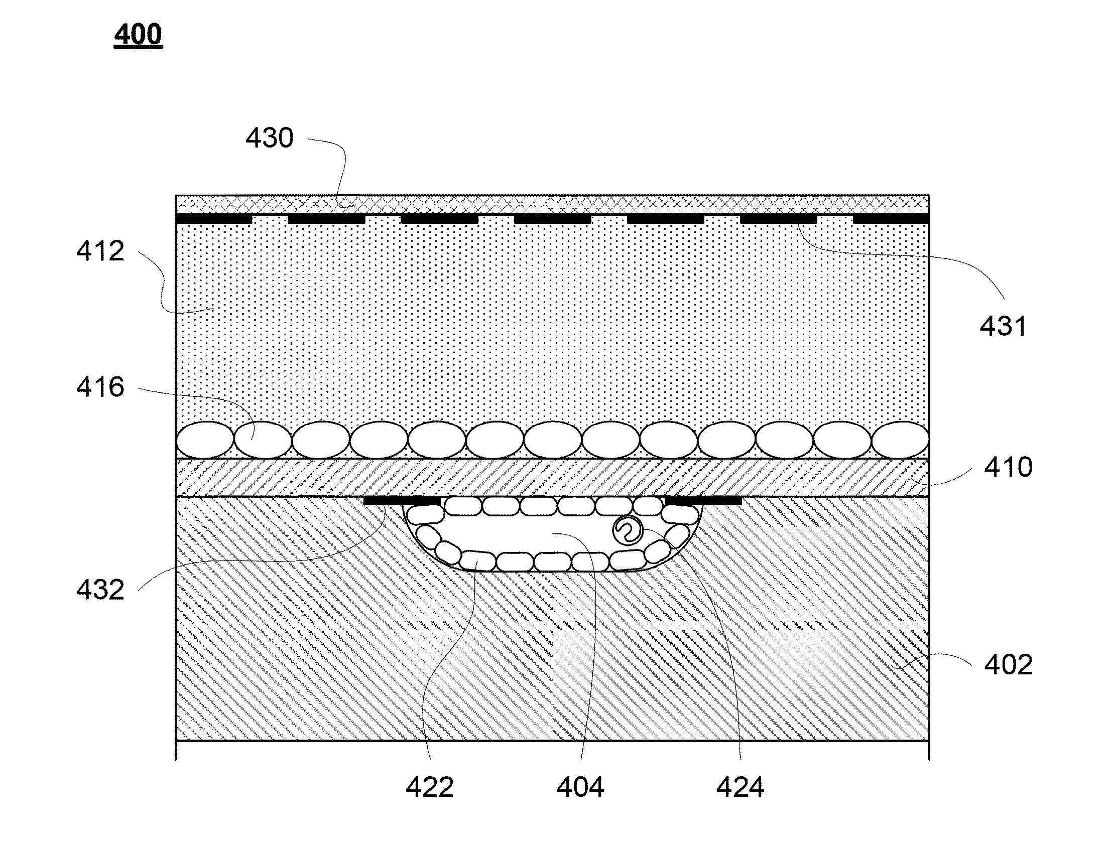
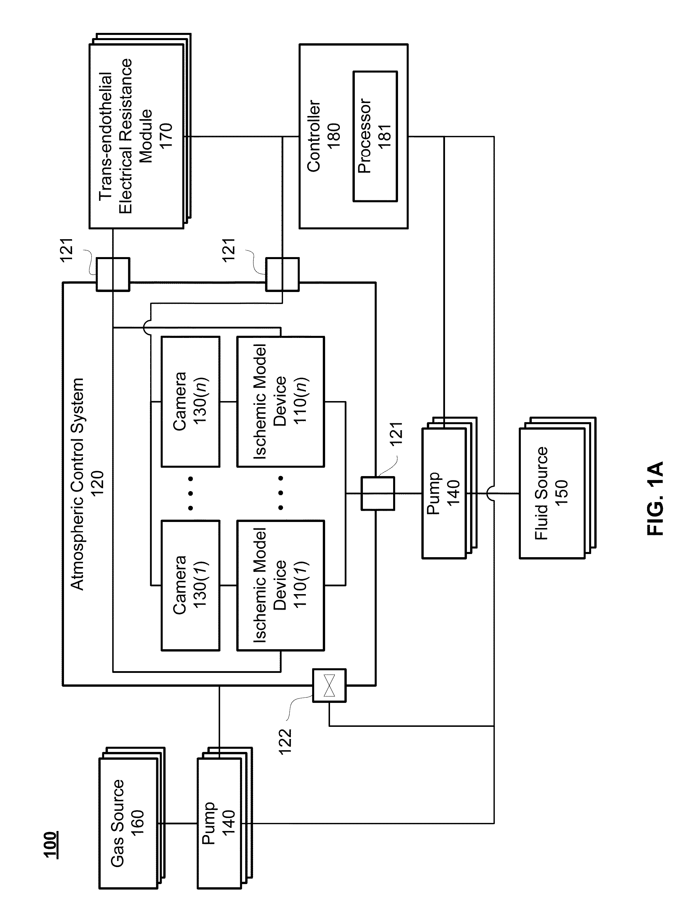
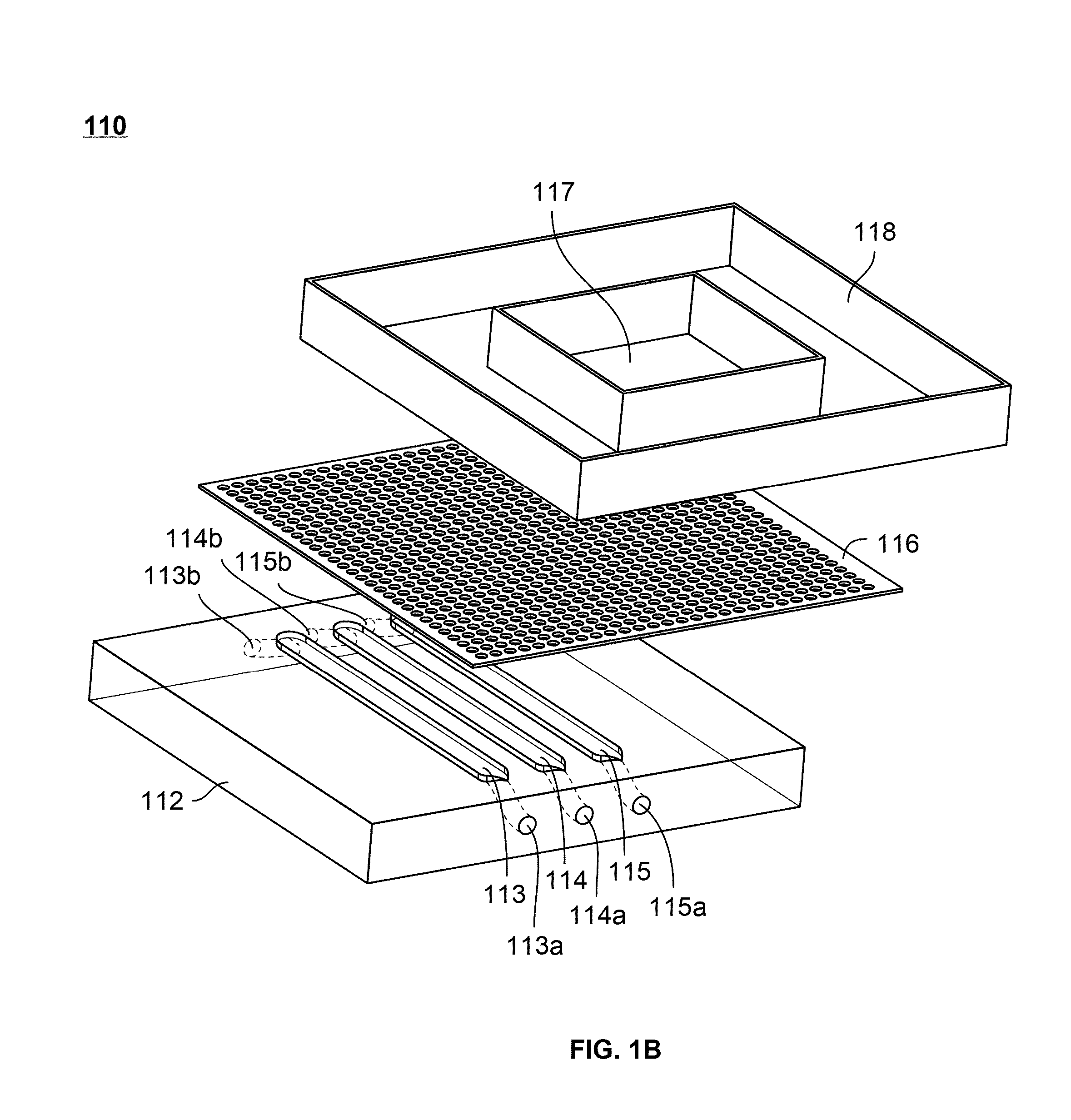
[0108]A microfluidic device for subjecting different neural cells to different environments can be produced according to the methods below. This device bears a neural compartment juxtaposed above three parallel microchannels. The neural compartment is separated from the microchannels by a microporous polyester membrane bonded irreversibly through a thin layer of silicone adhesive. FIG. 1 shows an exploded view of such a device.

[0109]The neural chamber accommodates a cell culture area of ˜0.5 cm2, close to the surface area of a section of adult rat brain. The channels are fabricated to have dimensions of 1 mm width, 250 μm height and 1.1 cm (length) separated from each other by 1 mm. The design of the neural chamber facilitates standard well-plate format of cell culture, which is simple, routine, and does not require continuous perfusion. The reservoir in the culture chamber holds ˜150 μl media. The membrane (10 μm thickness and por...


PUM

PropertyMeasurementUnit
diameteraaaaaaaaaa
diameteraaaaaaaaaa
temperatureaaaaaaaaaa

Abstract

This application provides devices for modeling ischemic stroke conditions. The devices can be used to culture neurons and to subject a first population of the neurons to low-oxygen conditions and a second population of neurons to normoxic conditions. The neurons are cultured on a porous barrier, and on the other side of the barrier run one or more fluid-filled channels. By flowing fluid with different oxygen levels through the channels, one can deliver desired oxygen concentrations to the cells nearest those channels.

Description

CROSS-REFERENCE TO RELATED PATENT APPLICATIONS[0001]This application claims priority to Provisional U.S. Patent Application 61 / 594,668, filed Feb. 3, 2012, which is incorporated herein by reference in its entirety.BACKGROUND OF THE DISCLOSURE[0002]Ischemic stroke occurs when neural tissue is damaged due to low oxygen levels. Magnetic resonance imaging detects three distinct areas in the brain of a stroke patient. The first, called the core, is the area that receives little or no oxygen, and experiences severe necrosis. A second area consists of normal tissue that receives sufficient oxygen. The third area falls between the core and the normal tissue, and is called the penumbra. Functionally, the penumbral area has compromised blood flow (CBF) and decreased oxygen consumption (CMRO2), which translates into neurons that are still viable but stressed. Over the course of several days following a stroke, the core gradually expands into the penumbra. Treatments for ischemic stroke are ext...

Claims


Application Information

Patent Timeline
Patent Type & Authority Patents(United States)
IPC IPC(8): G01N33/50G01N21/64C12M1/34C12M3/06
CPCG01N33/5058G01N33/5005C12M41/34G01N21/6486C12M23/16C12M35/02C12M35/08G01N33/5023G01N33/5026G01N2333/525G01N2333/5428G01N2333/545G01N2500/10G01N2510/00
Inventor ACHYUTA, ANILKUMAR HARAPANAHALLICUEVAS, JAVIERSUNDARAM, SHIVSHANKARKATNIK, CHRIS
Owner UNIV OF SOUTH FLORIDA
Learn More