
Homopolar motor-generator

a technology of motor generator and homopolar motor, which is applied in the direction of synchronous motors, magnetic circuit rotating parts, magnetic circuit shape/form/construction, etc., can solve the problems of general academic research or industrial developmen

Active Publication Date: 2014-12-23
ROTONIX CHINA CO LTD
View PDF50 Cites 4 Cited by
  • Summary
  • Abstract
  • Description
  • Claims
  • Application Information

AI Technical Summary

Benefits of technology

The patent text describes a type of motor that generates electricity and is controlled by a magnetic field. The motor has a rotor with multiple parts that work together to create a magnetic circuit. The rotor is enclosed in a stator that has a plurality of rings with slots. The motor has coils that are placed in the slots and create a magnetic field. This magnetic field interacts with the rotor to produce electricity. The motor is controlled by adjusting the field coils. The technical effect of this design is a more efficient motor that produces more electricity with less energy usage.

Problems solved by technology

Homopolar motors and homopolar motor-generators (“homopolar machines”) are not widely used in practice and have not generally been the subject of academic research or industrial development.

Method used


Image

  • Homopolar motor-generator
  • Homopolar motor-generator
  • Homopolar motor-generator

Examples


Embodiment Construction

[0028]The disclosure provided in the following pages describes examples of some embodiments of the invention. The designs, figures, and descriptions are non-limiting examples of certain embodiments of the invention. For example, other embodiments of the disclosed device may or may not include the features described herein. Moreover, disclosed advantages and benefits may apply to only certain embodiments of the invention and should not be used to limit the disclosed inventions.

[0029]As used herein, the term “coupled” includes direct and indirect connections. Moreover, where first and second devices are coupled, interposed devices including active devices may be located therebetween.

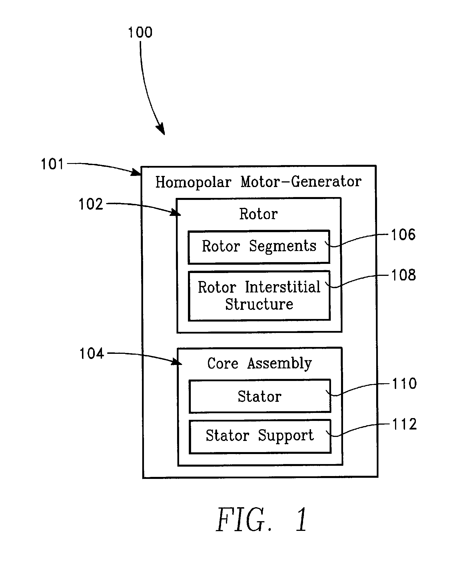
[0030]FIG. 1 shows a block diagram of a first homopolar machine 100. The first homopolar machine 101 includes a rotor 102 and a core assembly 104. The rotor includes multiple magnetic parts such as the rotor segments shown 106. In addition the rotor includes interstitial structure(s) 108. The core assembly...


PUM

PropertyMeasurementUnit
angleaaaaaaaaaa
angleaaaaaaaaaa
frequencyaaaaaaaaaa

Abstract

A motor-generator utilizes a multi-part rotor encircling a stator, the rotor including a plurality of rotor segments.

Description

PRIORITY CLAIM[0001]This application claims the benefit of Provisional Patent Application No. 61 / 568,126 filed Dec. 7, 2011 which is incorporated herein in its entirety and for all purposes.BACKGROUND OF THE INVENTION[0002]1. Field of Invention[0003]The present invention relates to an electric machine. In particular, a homopolar motor-generator is disclosed.[0004]2. Discussion of the Related Art[0005]Simple homopolar motors have been known since discovery of the Faraday motor in 1831. In Faraday's invention, a current carrying wire hanging alongside a bar magnet included in the circuit revolves about the magnet due to interaction of the two magnetic fields. Faraday's motor illustrates “Lorentz forces” which are at right angles to both the direction in which a charged particle is moving and the direction of an applied magnetic field. The simple application of the Lorentz force equation (‘crossing’ the direction, v, of the current into the direction, B, of the magnetic field) yields a...

Claims


Application Information

Patent Timeline
Patent Type & Authority Patents(United States)
IPC IPC(8): H02K47/06H02K47/04H02K47/14H02K47/20
CPCH02K1/2786H02K15/02H02K31/00H02K19/20H02K1/246H02K7/025H02K19/10Y10T29/49012H02K1/187H02K1/28H02K21/36
Inventor KALEV, CLAUDE MICHAELHOFMANN, HEATH F.
Owner ROTONIX CHINA CO LTD
Learn More