Intraocular lens (IOL) with multi optics assembly

a multi-optics, intra-ocular lens technology, applied in the field of ophthalmic lenses, can solve the problems of lens capsule loss, lens capsule collapse, and inability to prevent the loosening of the lens capsule, so as to prevent the collapse of the lens capsule

Inactive Publication Date: 2014-12-30
MIRLAY RAM SRIKANTH
View PDF4 Cites 19 Cited by
  • Summary
  • Abstract
  • Description
  • Claims
  • Application Information

AI Technical Summary

Benefits of technology

[0012]A primary objective of the embodiments herein is to develop a hinged IOL with multi-optics assembly provided with a scaffold structure to maintain the shape of an original natural lens and to keep the eye lens capsule intact in place thereby preventing the collapse of the lens capsule.
[0013]Another objective of the embodiments herein is to develop a hinged IOL with multi-optics assembly provided with a scaffold structure to allow a greater freedom for the movement of the optics or lenses with respect to hinge in response to the cilliary body muscle forces.

Problems solved by technology

IOL implantation carries several risks associated with eye surgeries, such as infection, lens rotation, inflammation, and night time halos.
Also the lens capsule loses its tone and starts collapsing over a period of time.
The greatest disadvantage of these IOLs is that they are not able to prevent the loosening of lens capsule.
At present, there is no system and method to keep the eye capsule intact.
The dual optics lenses are unsuccessful because of their low sensitivity, less visibility and degradative nature.
They fail to focus near objects, when required, especially, during reading and writing.
Further there is no system and method presently available to keep the eye capsule intact.

Method used


Image

  • Intraocular lens (IOL) with multi optics assembly
  • Intraocular lens (IOL) with multi optics assembly
  • Intraocular lens (IOL) with multi optics assembly

Examples


Embodiment Construction

[0042]In the following detailed description, a reference is made to the accompanying drawings that form a part hereof, and in which the specific embodiments that may be practiced is shown by way of illustration. These embodiments are described in sufficient detail to enable those skilled in the art to practice the embodiments and it is to be understood that the logical, mechanical and other changes may be made without departing from the scope of the embodiments. The following detailed description is therefore not to be taken in a limiting sense.

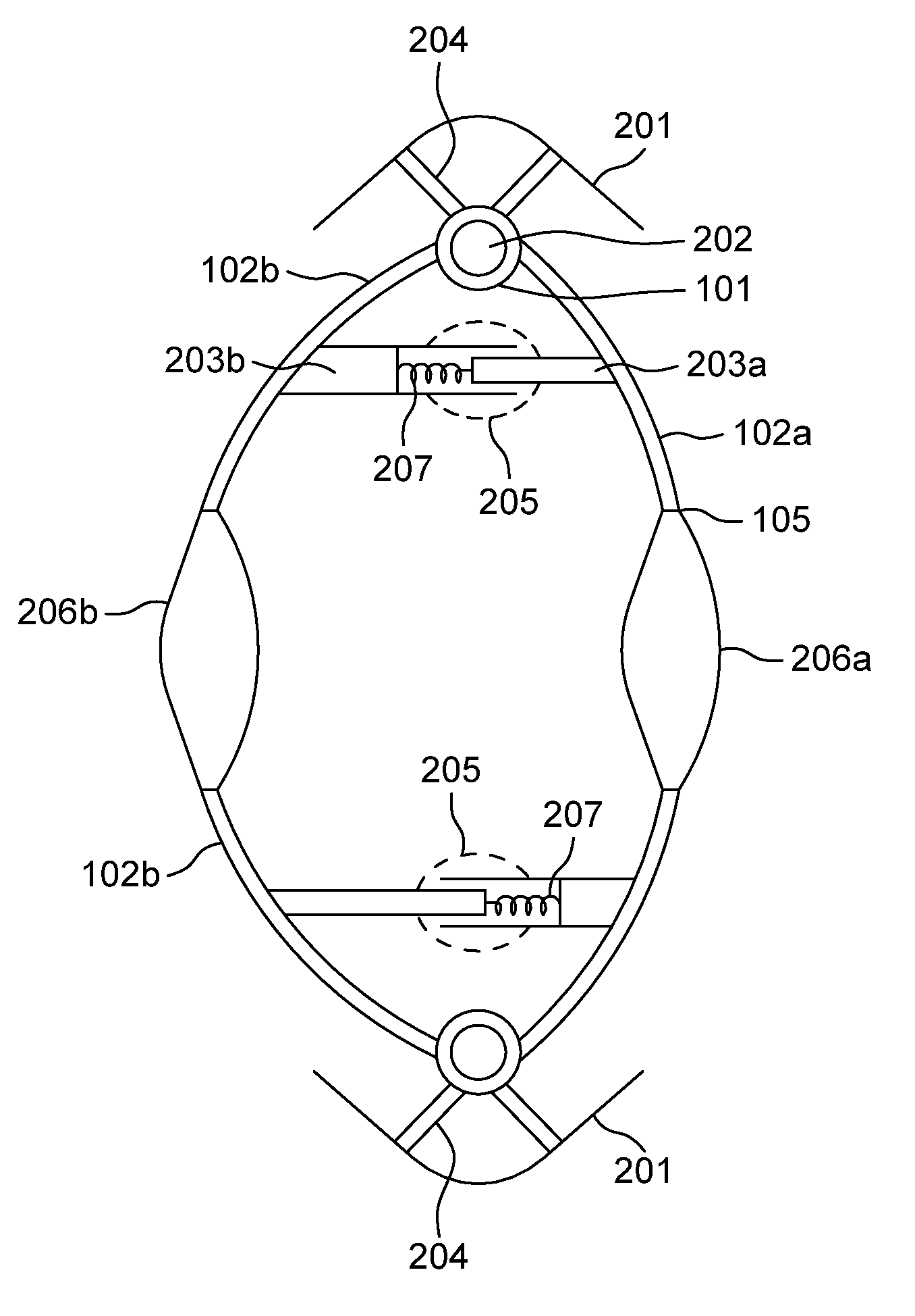
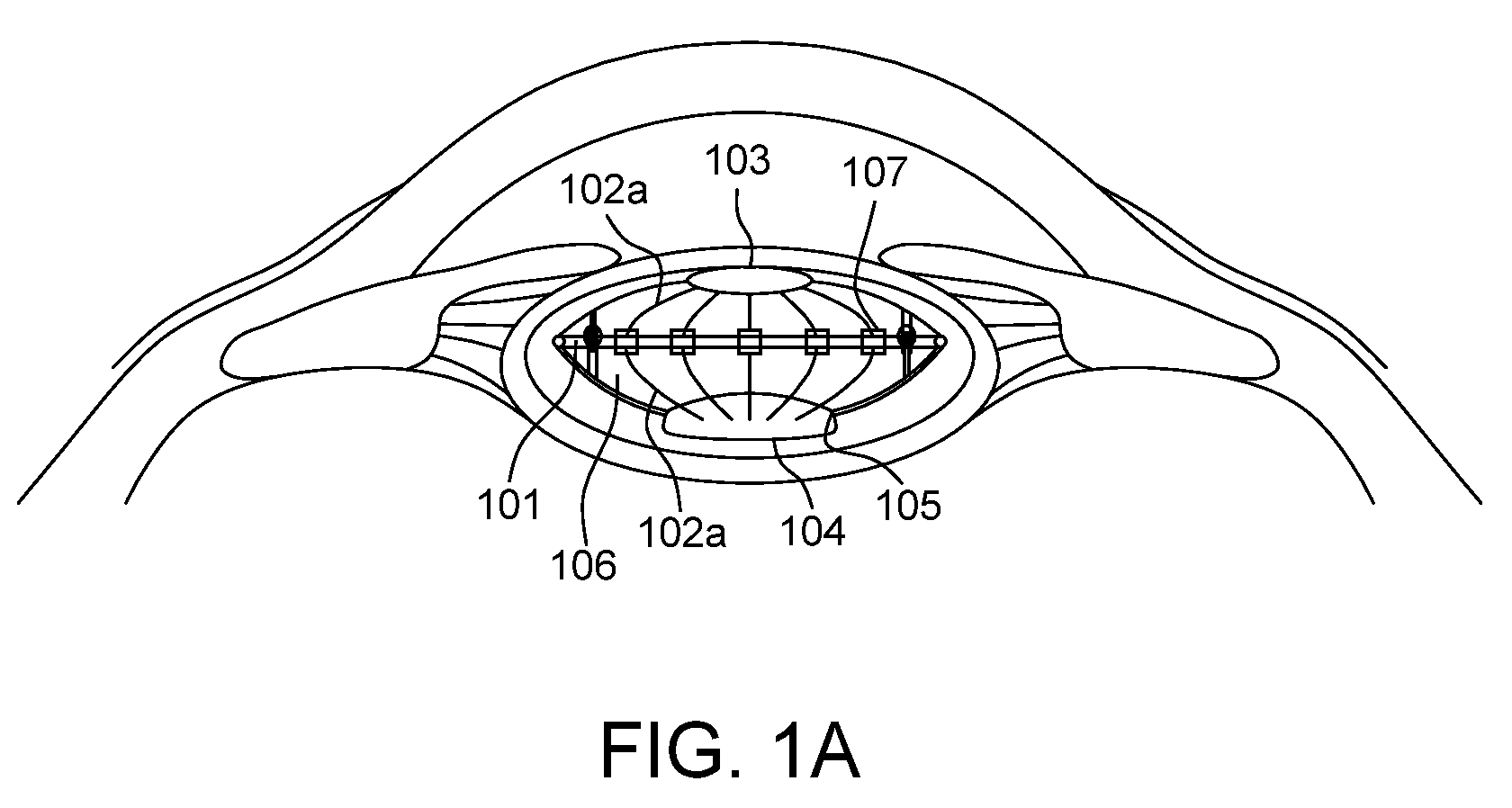
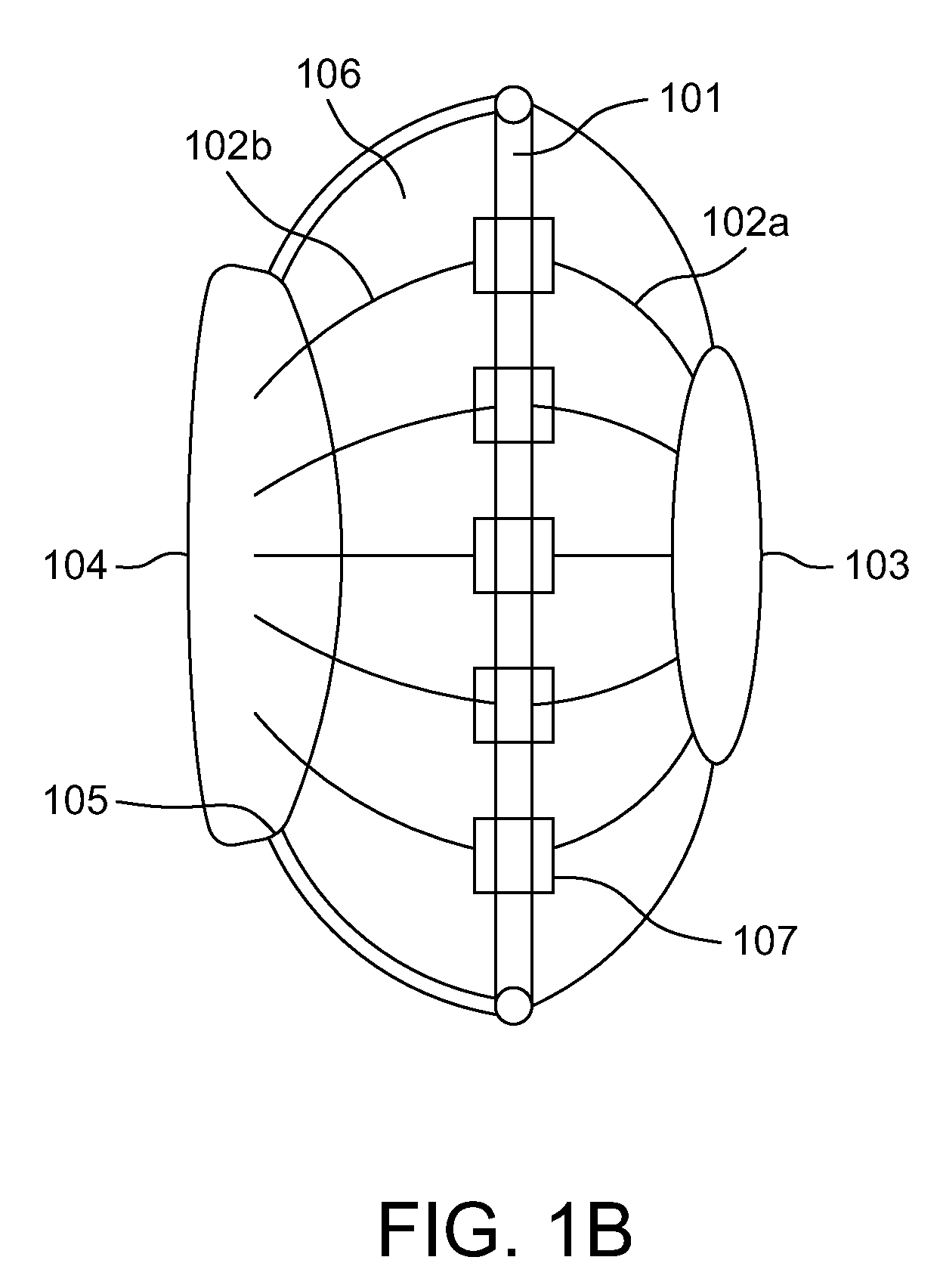
[0043]A multi-optics intraocular lens (IOL) scaffold assembly comprises a ring platform with a hinge protective umbrella arranged to encase and enclose the ring platform. A lens optics including an anterior optical lens and a posterior optical lens is supported by the ring platform. Anterior ribs are hinged to the ring platform to support the anterior optical lens and posterior ribs are hinged to the ring platform to support the posterior opt...


PUM


Abstract

The various embodiments of the present invention provide a multi-optics intraocular lens (IOL) scaffold assembly for incorporation into a capsular bag of an eye of a subject, provided with a ring platform and a protective umbrella. Several anterior and posterior ribs are hinged to the ring platform to support a posterior lens and an anterior lens. The dynamic spring elastic junctions are provided between the anterior and posterior ribs. The pendulum IOL assembly of the multi-optics intraocular lens (IOL) scaffold assembly enables a near vision of the objects using an optical system designed for a distance focusing in normal gaze. The pendulum IOL assembly has a posterior lens fixed to an equatorial ring platform and a secondary hanging lens provided with a weight at the lower end to act like a pendulum which swings with the posture of the eye.

Description

CROSS-REFERENCE TO RELATED APPLICATIONS[0001]This application is a National Phase Application of PCT International Application No. PCT / IN2011 / 000339, International Filing Date May 26, 2011, claiming priority of Indian Patent Applications Nos. 1608 / CHE / 2010, filed Jun. 10, 2010, and 1609 / CHE / 2010, filed Jun. 10, 2010, which are hereby incorporated by reference.BACKGROUND[0002]1. Technical field[0003]The embodiments herein generally relate to ophthalmic lenses and particularly to an implantable intra ocular lens to be implanted in a mammalian eye. The embodiments herein more particularly relates to a multi-optics intraocular lens (IOL) scaffold assembly for incorporation into a capsular bag of the eye, with dynamic junctions to keep an eye capsule of the eye intact and a pendulum intraocular lens assembly to adjust the vision for near and far objects.[0004]2. Description of the Related Art[0005]An intraocular lens (IOL) is an implanted lens in the mammalian eye, usually replacing the ...

Claims


Application Information

Patent Timeline
Patent Type & Authority Patents(United States)
IPC IPC(8): A61F2/16
CPCA61F2/1694A61F2/16A61F2/1624A61F2/1629A61F2/1648A61F2002/1681A61F2250/0065
Inventor MIRLAY, RAM, SRIKANTH
Owner MIRLAY RAM SRIKANTH
Why Eureka
Try Eureka