Active shutter glasses and three-dimensional image recognition unit

a three-dimensional image recognition and active shutter technology, applied in the field of active shutter glasses and three-dimensional image recognition units, can solve the problems of increasing the cost of an image display device, exceptionally poor display quality, etc., and achieve excellent display quality and improve contrast ratio

Inactive Publication Date: 2014-12-30
SHARP KK
View PDF5 Cites 3 Cited by
  • Summary
  • Abstract
  • Description
  • Claims
  • Application Information

AI Technical Summary

Benefits of technology

[0086]According to the active shutter glasses of the invention, an appropriate countermeasure for improving the contrast ratio in both of the right-eye and left-eye lenses is made, thereby visually recognizing a three-dimensional image with excellent display quality.

Problems solved by technology

In the anaglyph type, display quality is exceptionally poor bad and so-called crosstalk occurs.
It is also necessary to pattern and form a polarizing element, such as a λ / 2 plate, for each pixel, resulting in an increase in cost of an image display device.

Method used


Image

  • Active shutter glasses and three-dimensional image recognition unit
  • Active shutter glasses and three-dimensional image recognition unit
  • Active shutter glasses and three-dimensional image recognition unit

Examples


embodiment 1

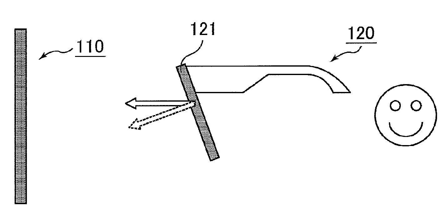
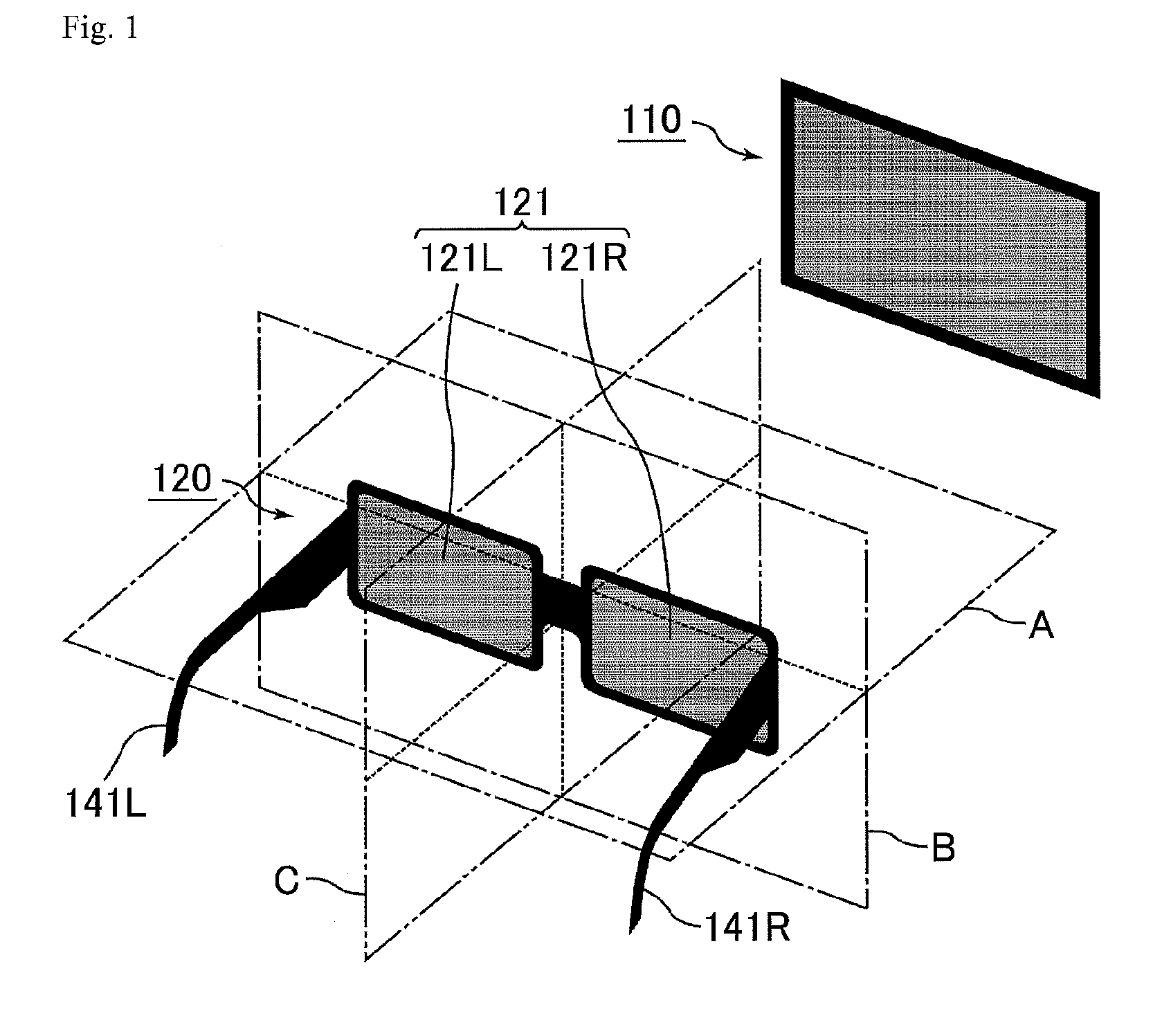
[0142]FIG. 1 is a schematic perspective view showing a three-dimensional image recognition unit of Embodiment 1. The three-dimensional image recognition unit of Embodiment 1 uses an active type. As shown in FIG. 1, the three-dimensional image recognition unit includes a 3D display device (image display device) 110 and active shutter glasses 120. The active shutter glasses 120 have two lenses of a right-eye lens 121R and a left-eye lens 121L. The active shutter glasses 120 of Embodiment 1 have a right temple 141R which is stretched in a direction substantially orthogonal to the lens surface of the right-eye lens 121R with the side of the right-eye lens 121R as a leading end, and a left temple 141L which is stretched in a direction substantially orthogonal to the lens surface of the left-eye lens 121L with the side of the left-eye lens 121L as a leading end. The stretching direction between the right temple 141R and the left temple 141L and the angle between the lens surface of the ri...

embodiment 2

[0192]A three-dimensional image recognition unit of Embodiment 2 has the same configuration as in Embodiment 1 except that the alignment direction and the optical characteristics of the liquid crystal cell of the active shutter glasses are different. In Embodiment 2, the direction of twist of the liquid crystal molecule group in the right-eye liquid crystal cell and the direction of twist of the liquid crystal molecule group in the left-eye liquid crystal cell are different from each other. Specifically, while the direction of twist of the liquid crystal molecule group in the right-eye liquid crystal cell is the counterclockwise direction (rotation to the left) when viewed from the observer side, and the direction of twist of the liquid crystal molecule group of the left-eye liquid crystal cell is the clockwise direction (rotation to the right) when viewed from the observer side.

[0193]FIGS. 20 and 21 are exploded perspective views showing the structure of active shutter glasses of E...

embodiment 3

[0217]A three-dimensional image recognition unit of Embodiment 3 is the same as Embodiment 1, except that the active shutter glasses have a different configuration. Embodiment 3 is different from Embodiment 1 in that a λ / 4 is further provided in the linearly polarizing plate on the observer-side surface of the 3D display device to form a circularly polarizing plate.

[0218]FIG. 26 is a schematic perspective view showing the arrangement relationship of a display device and active shutter glasses of a general three-dimensional image recognition unit. In a liquid crystal display device for a recent television, a VA mode or an IPS mode is generally used. As shown in FIG. 26, it is designed such that, in a VA mode or an IPS mode, a transmission axis 817t of a linearly polarizing element 817 closer to the observer side than a liquid crystal cell in a liquid crystal display device 810 becomes a longitudinal direction. This is because, even when special treatment, such as new addition of a me...


PUM

PropertyMeasurementUnit
azimuth angleaaaaaaaaaa

Abstract

Disclosed are active shutter glasses and a three-dimensional image recognition unit capable of visually recognizing a three-dimensional image with excellent display quality. The active shutter glasses are active shutter glasses for three-dimensional image recognition. The active shutter glasses comprise a right temple, a left temple, a right-eye lens, and a left-eye lens. The right-eye lens and the left-eye lens comprise liquid crystal cells. The right-eye lens and the left-eye lens have an inclination with respect to a state where the right-eye lens and the left-eye lens are arranged on the same plane, and are arranged on a surface orthogonal to a horizontal surface including the top surfaces of the right temple and the left temple. The direction of inclination of the right-eye lens is the direction in which the outer edge of the right-eye lens approaches an observer side at an azimuth angle φ2 in a range of ±45° with respect to an azimuth angle φ1, at which a contrast ratio has a maximum value, at a polar angle θ1 having an angle difference in a range of 2 to 17° from a line normal to the surface of the right-eye lens when not inclined. The direction of inclination of the left-eye lens is the direction in which the outer edge of the left-eye lens approaches the observer side at an azimuth angle φ4 in a range of ±45° with respect to an azimuth angle φ3, at which a contrast ratio has a maximum value, at a polar angle θ2 having an angle difference in a range of 2 to 17° from a line normal to the surface of the left-eye lens when not inclined.

Description

[0001]This application is the U.S. national phase of International Application No. PCT / JP2011 / 058894 filed 8 Apr. 2011 which designated the U.S. and claims priority to JP Patent Application No. 2010-155942 filed 8 Jul. 2010, the entire contents of each of which are hereby incorporated by reference.TECHNICAL FIELD[0002]The present invention relates to active shutter glasses and a three-dimensional image recognition unit. In particular, the present invention relates to active shutter glasses which express a 3D image through opening and closing of a shutter using liquid crystal cells, and a three-dimensional image recognition unit including the active shutter glasses.BACKGROUND ART[0003]As a type of a three-dimensional image recognition unit using glasses, an anaglyph type, a passive type, an active type, and the like are known. In the anaglyph type, display quality is exceptionally poor bad and so-called crosstalk occurs. Both the passive and active types use polarized glasses.[0004]I...

Claims


Application Information

Patent Timeline
Patent Type & Authority Patents(United States)
IPC IPC(8): G03B35/26G02B27/22G02F1/1335G02C7/10H04N13/04
CPCG03B35/26H04N13/0438H04N2213/008G02C7/101G02B27/2264H04N13/341G02B30/24
Inventor UEKI, SHUNNAKAMURA, KOZONAKAHARA, TAKAHIRO
Owner SHARP KK
Why Eureka
Try Eureka