
Safety extension base and control method thereof

a safety extension and control method technology, applied in the direction of electric controllers, program control, electric programme control, etc., can solve the problems of human and material damage according to the malfunction, the state of the system is not properly provided to the extension base, and malfunctions, so as to prevent human and material damag

Active Publication Date: 2014-12-30
LS IND SYETEMS CO LTD
View PDF15 Cites 0 Cited by
  • Summary
  • Abstract
  • Description
  • Claims
  • Application Information

AI Technical Summary

Benefits of technology

The present invention is about a system that allows for a separate part of a programmable logic controller (PLC) to remain safe and control the system, even if the main part of the PLC malfunctions or has other issues. This separation also helps to protect devices and prevent damage to humans and materials caused by the malfunction of the main part of the system.

Problems solved by technology

However, in a case a defect occurs in the conventional PLC system, the main base recognizes the occurrence of the defect and provides the state of the system to the extension bases.
Therefore, in a case a defect occurs in the conventional PLC system, the main base does not recognize or slowly recognizes the occurrence of the defect, and hence the state of the system is not properly provided to the extension bases.
Accordingly, malfunction may occur in devices mounted to the extension bases, and human and material damage according to the malfunction may be caused.
Therefore, the extension base does not independently operate, and accordingly, the system is exposed to risk cause by the malfunction.

Method used


Image

  • Safety extension base and control method thereof
  • Safety extension base and control method thereof
  • Safety extension base and control method thereof

Examples


Embodiment Construction

[0030]The present invention is described more fully hereinafter with reference to the accompanying drawings, in which embodiments of the present invention are shown. This present invention may, however, be embodied in many different forms and should not be construed as limited to the embodiments set forth herein. Rather, these embodiments are provided so that this disclosure is thorough, and will fully convey the scope of the present invention to those skilled in the art.

[0031]FIG. 3 is a diagram illustrating a configuration in which a safety-extension base is connected in a single PLC (Programmable logic controller) system according to an embodiment of the present invention.

[0032]Referring to FIG. 3, the safety-extension base 110 according to this embodiment is connected together with a plurality of general extension bases 120 to a main base 100. The safety-extension base 110 and the plurality of general extension bases 120 communicate data with the main base 100 through a series o...


PUM


Abstract

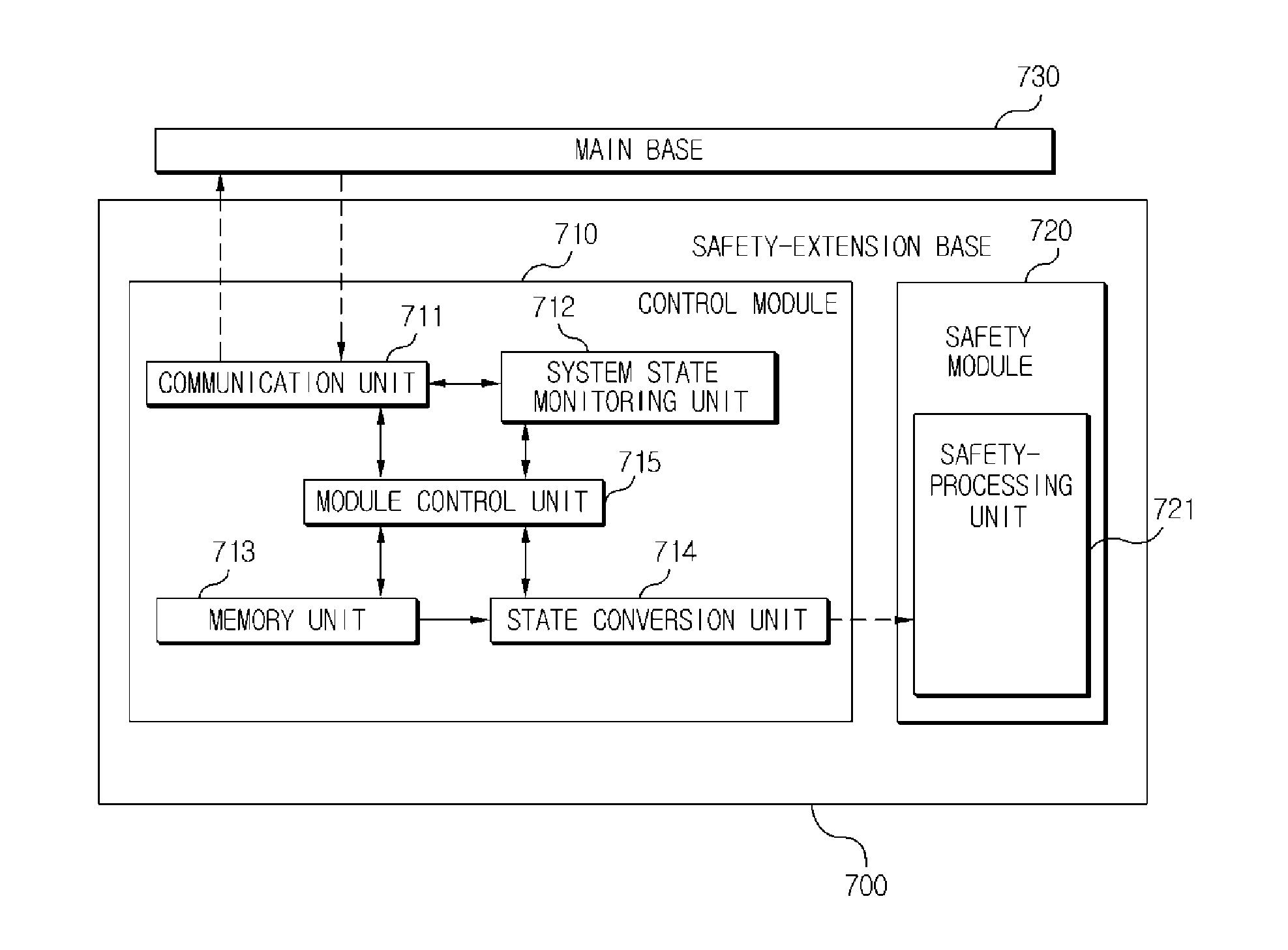
A safety-extension base connected to a main base and a control method thereof are disclosed, the base includes a communication unit, a system state monitoring unit, a module control unit, a memory unit, a state conversion unit and a safety-processing unit. The communication unit performs data communication with the main base. The system state monitoring unit monitors a state of the PLC system. The module control unit controls a general operation of the safety-extension base and outputs different cases of control signals. The memory unit stores the data transmitted from the main base and a program and information. The state conversion unit converts the state of the safety-extension base into the normal state or safety state. The safety-processing unit performs a control of the safety-extension base.

Description

CROSS-REFERENCE TO RELATED APPLICATIONS[0001]This application is the National Stage filing under 35 U.S.C. 371 of International Application No. PCT / KR2011 / 000389, filed on Jan. 19, 2011, which claims the benefit of earlier filing date and right of priority to Korean Application No. 10-2010-0005209, filed on Jan. 20, 2010, the contents of which are all hereby incorporated by reference herein in their entirety.TECHNICAL FIELD[0002]The present invention relates to control of a safety-extension base, and more particularly, to a safety-extension base and a control method thereof, in which the safety-extension base is independently maintained and controlled in a safety state, separately from control of a main base, in a programmable logic controller (PLC) system.BACKGROUND ART[0003]A programmable logic controller (PLC) is an electronic device connected to various devices so as to systematically control these devices. A PLC system uses a programmable memory to perform a special function su...

Claims


Application Information

Patent Timeline
Patent Type & Authority Patents(United States)
IPC IPC(8): G05B11/01G05B19/18G05B9/02G06F11/07G05B19/05
CPCG05B19/058G06F11/0796G05B9/02G05B2219/34465G05B19/05G05B19/056G06F9/4406G06F9/4496
Inventor BAEK, SEUNG, JAE
Owner LS IND SYETEMS CO LTD
Learn More