Eureka AIR delivers breakthrough ideas for toughest innovation challenges, trusted by R&D personnel around the world.

Flow battery stack liquid guide plate structure and application

A technology of liquid flow battery and liquid guide plate, which is applied in the direction of fuel cells, regenerative fuel cells, circuits, etc., to avoid material damage and improve the reliability of stacks

Pending Publication Date: 2022-05-20
DALIAN INST OF CHEM PHYSICS CHINESE ACAD OF SCI
View PDF0 Cites 0 Cited by
  • Summary
  • Abstract
  • Description
  • Claims
  • Application Information

AI Technical Summary

Problems solved by technology

The invention provides a liquid flow battery cell stack liquid guide plate structure

Method used


Image

  • Flow battery stack liquid guide plate structure and application
  • Flow battery stack liquid guide plate structure and application
  • Flow battery stack liquid guide plate structure and application

Examples


Embodiment 1

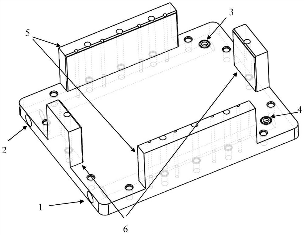
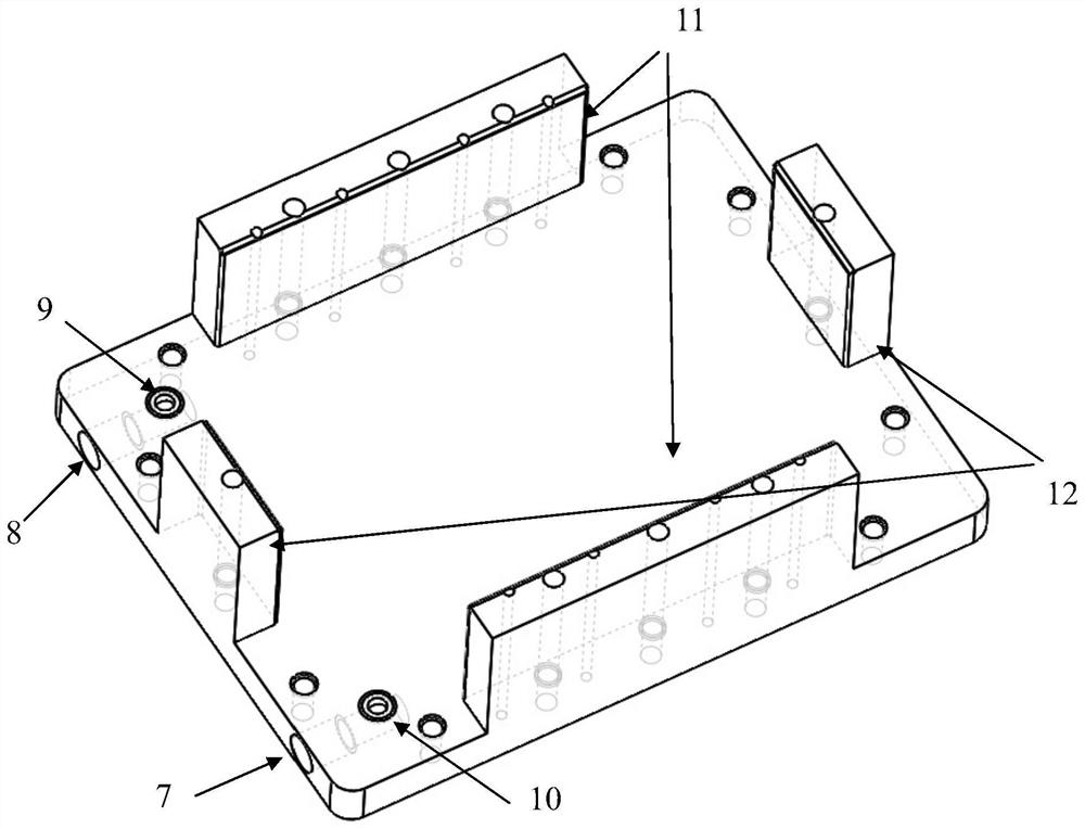
[0034] A stack structure of a liquid flow battery, which consists of aluminum or steel metal end plates on both sides of the stack, figure 1 with figure 2 The matching PVC liquid guide plates A1 and B1, copper collector plates and several single cells are connected in series. Among them, the positive electrolyte flows into the stack through the positive electrolyte inlet 1, and then flows into the positive electrolyte inlet 4 on the electrode frame from the positive electrolyte distribution port 4 flowing into the electrode frame, flows through the electrodes of each single cell, and then aggregates through the outflow electrodes The positive electrolyte distribution port 10 of the frame flows into the liquid guide plate, and then flows out of the stack through the positive electrolyte outlet 7; the negative electrolyte flows into the stack through the negative electrolyte inlet 2, and then flows into the negative electrolyte distribution port 3 of the electrode frame Flow i...

Embodiment 2

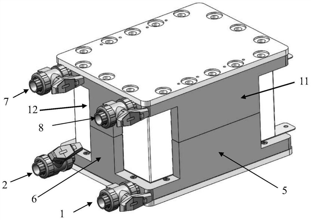
[0041] A stack structure of a liquid flow battery, which consists of aluminum or steel metal end plates on both sides of the stack, Figure 4 with Figure 5 The matching PVC liquid guide plates A2 and B2, copper current collector plates and several single cells are connected in series. Among them, the positive electrolyte flows into the cell stack through the positive electrolyte inlet 1, and then flows into the positive electrolyte liquid inlet port 4 on the electrode frame from the positive electrolyte distribution port 4 flowing into the electrode frame, and flows through the electrodes of each single cell before being aggregated. The positive electrode electrolyte distribution port 10 flowing out of the electrode frame flows into the liquid guide plate, and then flows out of the stack through the positive electrode electrolyte outlet 7; the negative electrode electrolyte flows into the stack through the negative electrode electrolyte inlet 2, and then the negative electrod...


PUM


Abstract

The invention relates to a flow cell stack liquid guide plate structure, which is characterized in that strip-shaped limiting blocks perpendicular to the surface of a flat plate are respectively arranged at the edges of four sides of the surface of one side of one liquid guide plate of a flow cell stack along the side length direction, and the other liquid guide plate is provided with corresponding strip-shaped limiting blocks and / or strip-shaped limiting blocks staggered with the strip-shaped limiting blocks on the liquid guide plate. And a corresponding through hole is formed in the corresponding limiting block and penetrates through the positioning block and the liquid guide plate. In the process of assembling and pressing the galvanic pile, the limiting block can well limit the transverse displacement of the electrode frame, so that the pulling force on the material caused by the extrusion offset of the electrode frame is prevented, the sealing and positioning requirements are better met, and the reliability and the assembly success rate of the galvanic pile are improved. In addition, the limiting block limits the pressing thickness of the galvanic pile, and material damage caused by overpressure is avoided.

Description

technical field [0001] The invention relates to a structure of a liquid flow battery stack, in particular to the structure of a liquid guide plate in a liquid flow battery stack. Background technique [0002] With the ever-changing and rapid development of the economy and society, the demand for energy from all walks of life has increased sharply, which puts forward higher requirements for the stability of the power grid. The real-time balance of source and load, the application of renewable energy and the upgrading of the energy structure promote the development of the State Grid towards a smarter, more complete and stronger direction. For the above new requirements, new technologies are needed to improve the flexibility of the power grid and meet the needs of large-scale peak regulation and frequency regulation. Energy storage technology emerges as the times require, through real-time dispatch of electric energy in the grid to adjust frequency and peak in time; through re...

Claims


Application Information

Patent Timeline
IPC IPC(8): H01M8/2483H01M8/18
CPCH01M8/2483H01M8/188Y02E60/50
Inventor 邢枫李先锋张华民
Owner DALIAN INST OF CHEM PHYSICS CHINESE ACAD OF SCI
Why Eureka
Eureka Blog
Learn More