Escapement system for a sprung balance resonator
a technology of sprung balance and escape system, which is applied in the direction of electromechanical clocks, electric windings, instruments, etc., can solve the problems of reducing the power reserve of the timepiece, affecting the performance of the timepiece, and causing friction and/or lowering the aerodynamics of the timepi
- Summary
- Abstract
- Description
- Claims
- Application Information
AI Technical Summary
Benefits of technology
Problems solved by technology
Method used
Image
Examples
first embodiment
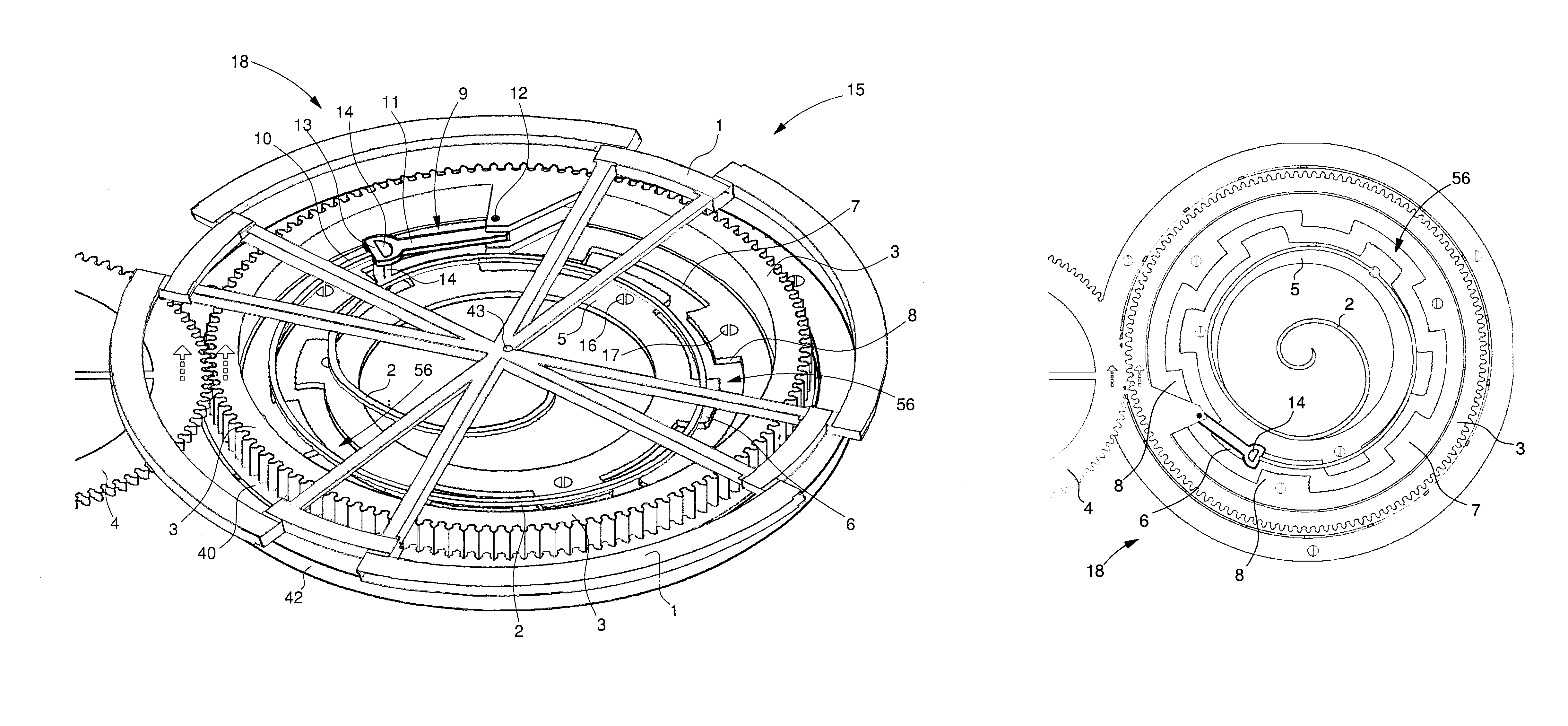
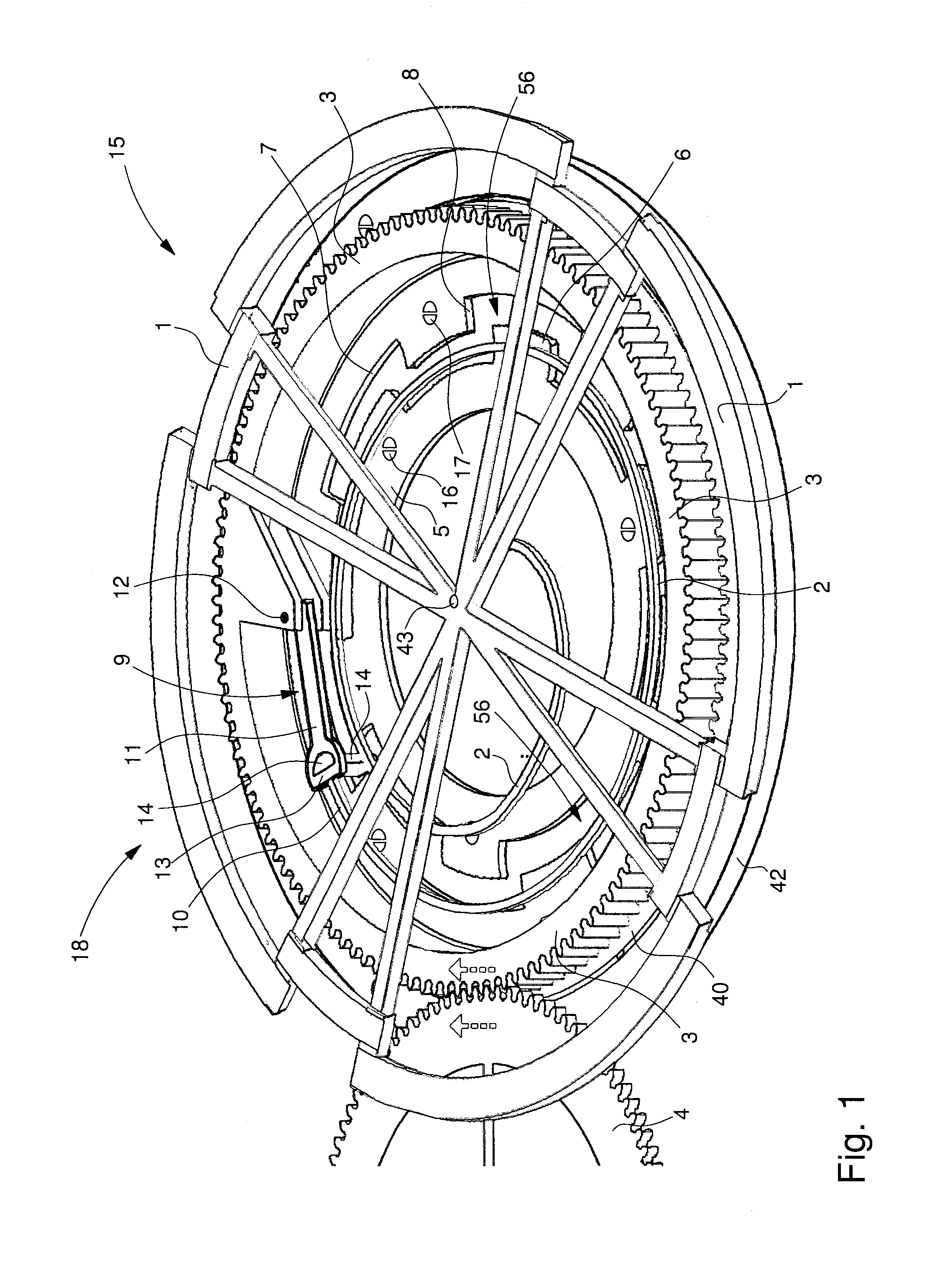
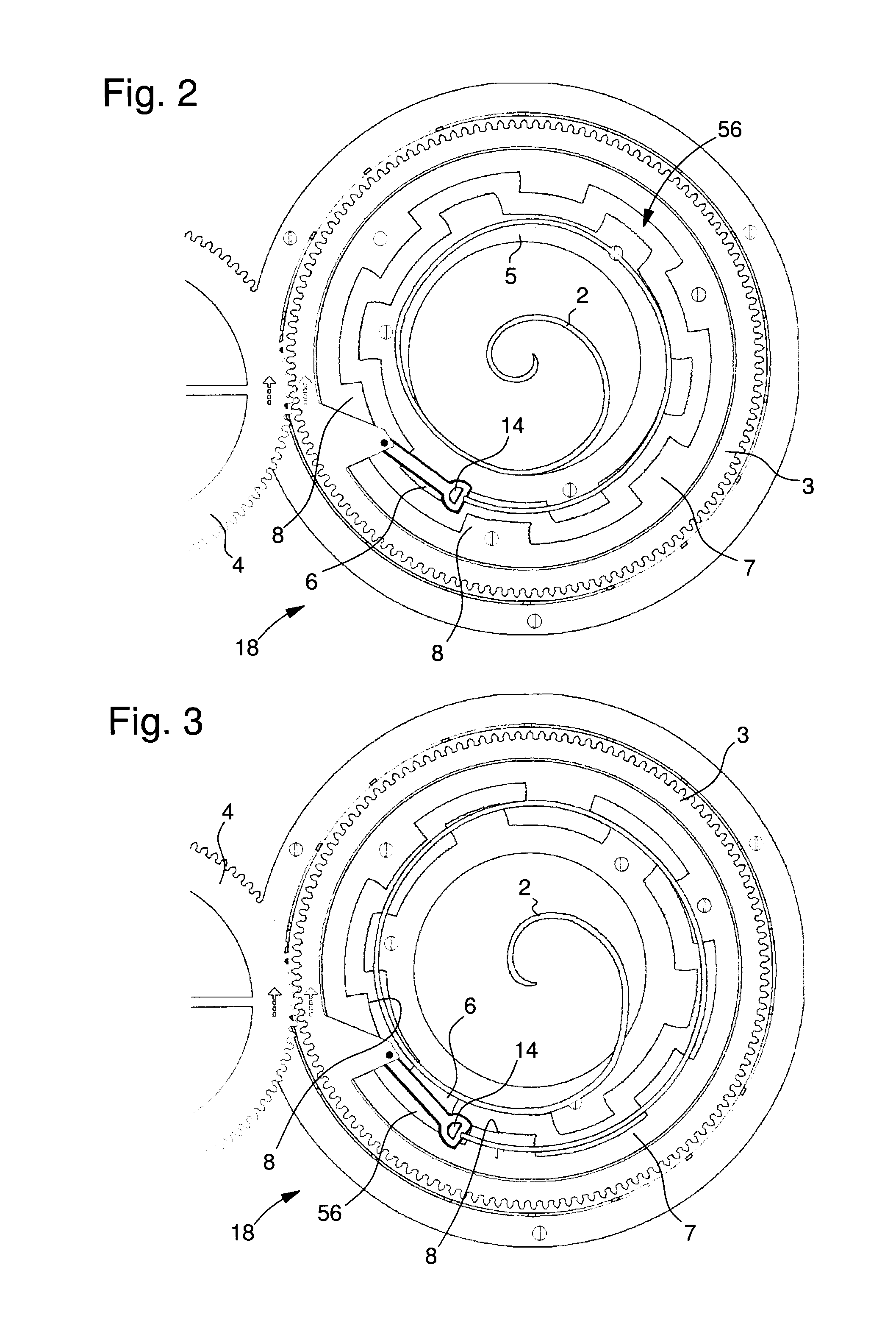
[0042]the present invention is illustrated in FIG. 1 which is a perspective view of an oscillator of the invention, i.e. an escapement system 18 coupled to a sprung balance resonator 15. Resonator 15 according to the invention includes a balance 1 associated with a balance spring 2.
[0043]Balance spring 2 is only represented by a limited number of coils for the clarity of the drawing and to avoid concealing the elements underneath said spring. However, balance spring 2 may, of course, include a larger number of coils without departing from the scope of the invention. The inner end 50 of balance spring 2 is fixed to an arbour 43, for example by means of an integral collet (shown more clearly in FIG. 9). The example illustrated in FIG. 1 shows that balance 1 is also fixed to arbour 43.
[0044]According to the invention, escapement system 18 includes a moving escape wheel 3 arranged coaxially to resonator 15. In the example illustrated in FIG. 1, moving escape wheel 3 is driven by a secon...
third embodiment
[0062]escapement system 22 according to the invention is illustrated in FIGS. 11 to 13. Escapement system 22 differs from the two preceding embodiments in that the first and second fixed wheels 5 and 7 are made in a single piece.
[0063]In order to better explain this third embodiment, FIGS. 12 and 13 are respectively cross-sections taken along XII and XIII of FIG. 11. Resonator 23 of the third embodiment is of the same type as resonator 15, 20 of the first two embodiments. Balance 1 is thus seen again, fitted with poising screw 70 and connected to arbour 43 by means of four arms 71. Arbour 43 is pivotally mounted between bridge 44 and a bearing 72 integral with a unit 51 which incorporates, in a single piece, the outer teeth 6 and inner teeth 8 formed, in the first two embodiments, by fixed wheels 5 and 7.
[0064]Balance 1 is associated with balance spring 24 which includes more coils than balance spring 2 of the first embodiment and in which the end of the inner coil 50 is fixed to ar...
fourth embodiment
[0066]It is also observed in FIG. 14 that the first teeth 72 have a smaller inner diameter than that of the second teeth 73. In the fourth embodiment, securing device 74 differs from device 9 of the first three embodiments. Thus, securing device 74 includes a lever 75 hinged on balance spring stud 12 carried by moving escape wheel 3. Lever 75 carries a first arm 76 at the end of which there are fixed the outer end 10 of balance spring 2 and a first impulse pin 77 arranged to cooperate with the first teeth 72 of first fixed wheel 70. Lever 75 also carries a second arm 78 at the end of which there is fixed a second impulse pin 79 arranged to cooperate with the second teeth 73 of second fixed wheel 71. Preferably, each impulse pin 77, 79 is formed of the same material as balance spring 2 or is ruby-based.
[0067]FIG. 14 shows a balance spring 2 of the type in the first embodiment in maximum expansion. The first impulse pin 77 is held locked against a first tooth 72 of the first fixed whe...
PUM
 Abstract
Description
Claims
Application Information
 - R&D
- Intellectual Property
- Life Sciences
- Materials
- Tech Scout
- Unparalleled Data Quality
- Higher Quality Content
- 60% Fewer Hallucinations
Browse by: Latest US Patents, China's latest patents, Technical Efficacy Thesaurus, Application Domain, Technology Topic, Popular Technical Reports.
© 2025 PatSnap. All rights reserved.Legal|Privacy policy|Modern Slavery Act Transparency Statement|Sitemap|About US| Contact US: help@patsnap.com


