Gas pressure generator

A generator and air pressure technology, which is applied to machines/engines, rotary piston engines, rotary or oscillating piston engines, etc., can solve the problems of complex equipment, low energy utilization rate, and large energy loss in the air pressure system, and achieve the utilization rate. The effect of high, performance improvement, and speed increase

Inactive Publication Date: 2014-11-19
邓雪明
View PDF7 Cites 4 Cited by
  • Summary
  • Abstract
  • Description
  • Claims
  • Application Information

AI Technical Summary

Problems solved by technology

The power system requires a control system to control the speed, the equipment required for power generation is complex, the energy loss of the air pressure system is large during power generation, and the energy utilization rate is low

Method used


Image

  • Gas pressure generator

Examples


Embodiment Construction

[0016] The present invention will be further described in detail below in conjunction with the accompanying drawings, so that those skilled in the art can implement it with reference to the description.

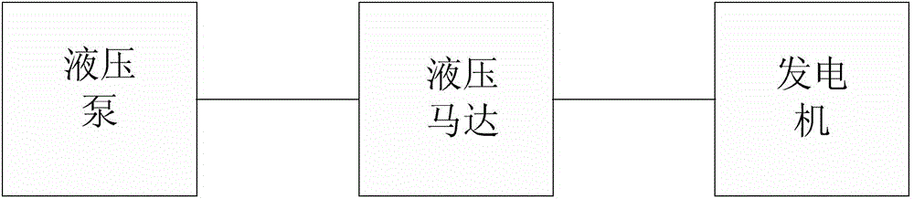
[0017] Such as figure 1 As shown, the present invention provides a pneumatic generator, comprising: comprising:

[0018] A low-speed air pump or air compressor that provides a power source; an air motor driven by high-pressure gas that converts the air pressure energy provided by the low-speed air pump or air compressor into mechanical energy, including: a rotating body with a cavity inside; Connected to the fluid delivery main shaft inside the rotating body; it has axial fluid relative movement with the fluid delivery main shaft, and squeezes the follower wheel on the inner wall of the cavity, and the air motor repressurizes the gas flowing in from the air pump; one air motor provides A generator that converts mechanical energy into electrical energy.

[0019] The air pres...


PUM


Abstract

The invention discloses a gas pressure generator which comprises a low-rotating-speed gas pressure pump, a gas pressure motor and a generator, wherein the low-rotating-speed gas pressure pump is used for providing a power source and pressurizing inflowing gas; the gas pressure motor is used for converting gas pressure energy provided by the low-rotating-speed gas pressure pump into mechanical energy, is driven by high-pressure gas, and comprises a rotator with a cavity inside, a gas delivery spindle connected into the rotator, and a following wheel performing axial gas movement relative to the gas delivery spindle and squeezing the inner wall of the cavity; the gas pressure motor pressurizes gas flowing from the gas pressure pump again; the generator is used for converting the mechanical energy provided by the gas pressure motor into electric energy. The gas pressure generator provided by the invention can utilize low-rotating-speed gas of the gas pressure motor as kinetic energy to generate electricity, so that the energy utilization efficiency and the energy conversion efficiency are improved.

Description

technical field [0001] The invention relates to a pneumatic generator. Background technique [0002] The power system of the current air pressure generator adopts a constant rotating speed to control the constant rotation of the generator rotor and cut the magnetic field lines. The power system requires a control system to control the speed, the equipment required for power generation is complex, the energy loss of the air pressure system is large during power generation, and the energy utilization rate is low. Contents of the invention [0003] The present invention aims at above-mentioned deficiency, proposes a kind of pneumatic generator. [0004] The technical scheme provided by the invention is: [0005] A pneumatic generator, characterized in that it comprises: [0006] A low speed air pump or air compressor to provide the power source; [0007] A high-pressure gas-driven air motor that converts the air pressure energy provided by the low-speed air pump or air co...

Claims


Application Information

Patent Timeline
Patent Type & Authority Applications(China)
IPC IPC(8): F01C1/00F01C13/00H02K7/18
Inventor 邓雪明
Owner 邓雪明
Why Eureka
Try Eureka