Escapement system for a sprung balance resonator

a technology of sprung balance and escapement system, which is applied in the direction of escapement, frequency stabilisation mechanism, instruments, etc., can solve the problems of reducing the power reserve of the timepiece, affecting the stability of the timepiece, and causing friction and/or lowering the aerodynamics of the timepi

Active Publication Date: 2014-10-16
MONTRES BREGUET
View PDF3 Cites 4 Cited by
  • Summary
  • Abstract
  • Description
  • Claims
  • Application Information

AI Technical Summary

Benefits of technology

[0010]It is an object of the present invention to overcome all of part of the aforecited drawbacks by proposing an alternative escapement system for a sprung balance resonator which allows the mechanical energy Em of said resonator to be increased, while avoiding the aforementioned pitfalls.

Problems solved by technology

However the increase in these parameters causes great difficulties.
Indeed, the increase in the inertia J of the balance tends to increase its weight which causes unwanted dry friction and / or lowers its aerodynamics.
Further, the increase in oscillation frequency f requires a considerable increase in virtual power which is liable to decrease the power reserve of the timepiece.
It is also clear that the increase in oscillation frequency f necessarily means that the escapement functions become shorter and shorter which represents a real kinematic and tribological challenge.

Method used


Image

  • Escapement system for a sprung balance resonator
  • Escapement system for a sprung balance resonator
  • Escapement system for a sprung balance resonator

Examples


first embodiment

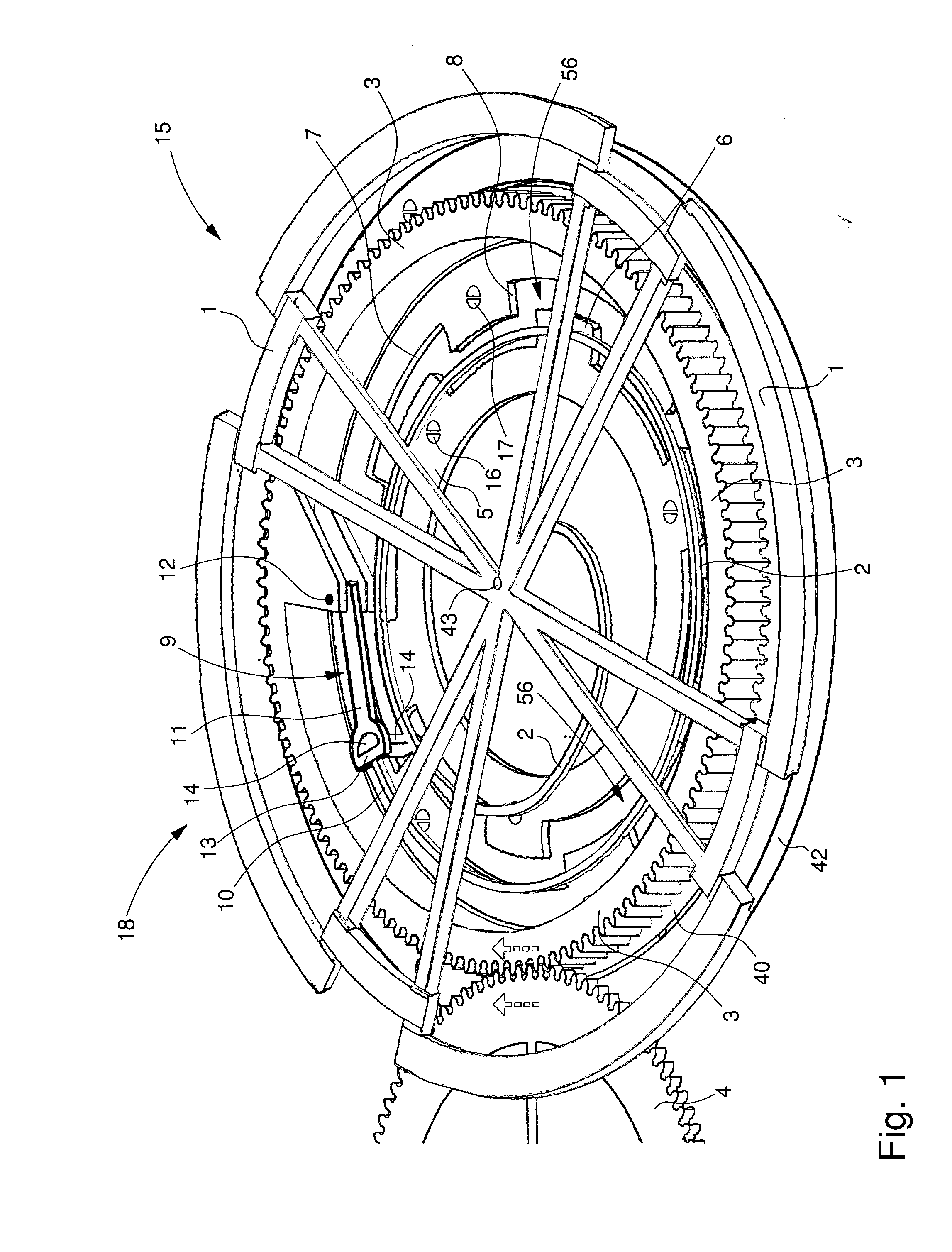
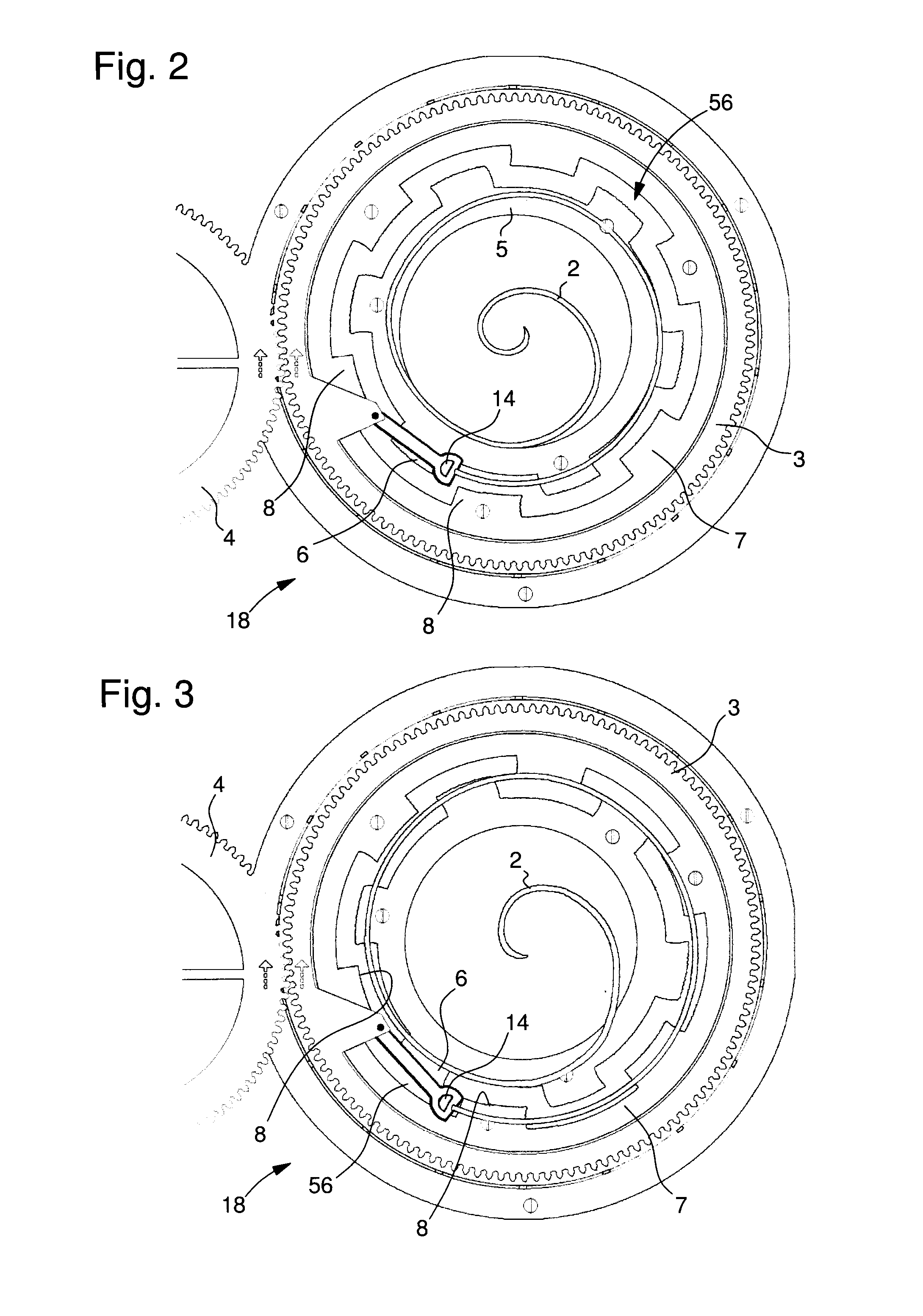
[0041]the present invention is illustrated in FIG. 1 which is a perspective view of an oscillator of the invention, i.e. an escapement system 18 coupled to a sprung balance resonator 15. Resonator 15 according to the invention includes a balance 1 associated with a balance spring 2.

[0042]Balance spring 2 is only represented by a limited number of coils for the clarity of the drawing and to avoid concealing the elements underneath said spring. However, balance spring 2 may, of course, include a larger number of coils without departing from the scope of the invention. The inner end 50 of balance spring 2 is fixed to an arbour 43, for example by means of an integral collet (shown more clearly in FIG. 9). The example illustrated in FIG. 1 shows that balance 1 is also fixed to arbour 43.

[0043]According to the invention, escapement system 18 includes a moving escape wheel 3 arranged coaxially to resonator 15. In the example illustrated in FIG. 1, moving escape wheel 3 is driven by a secon...

third embodiment

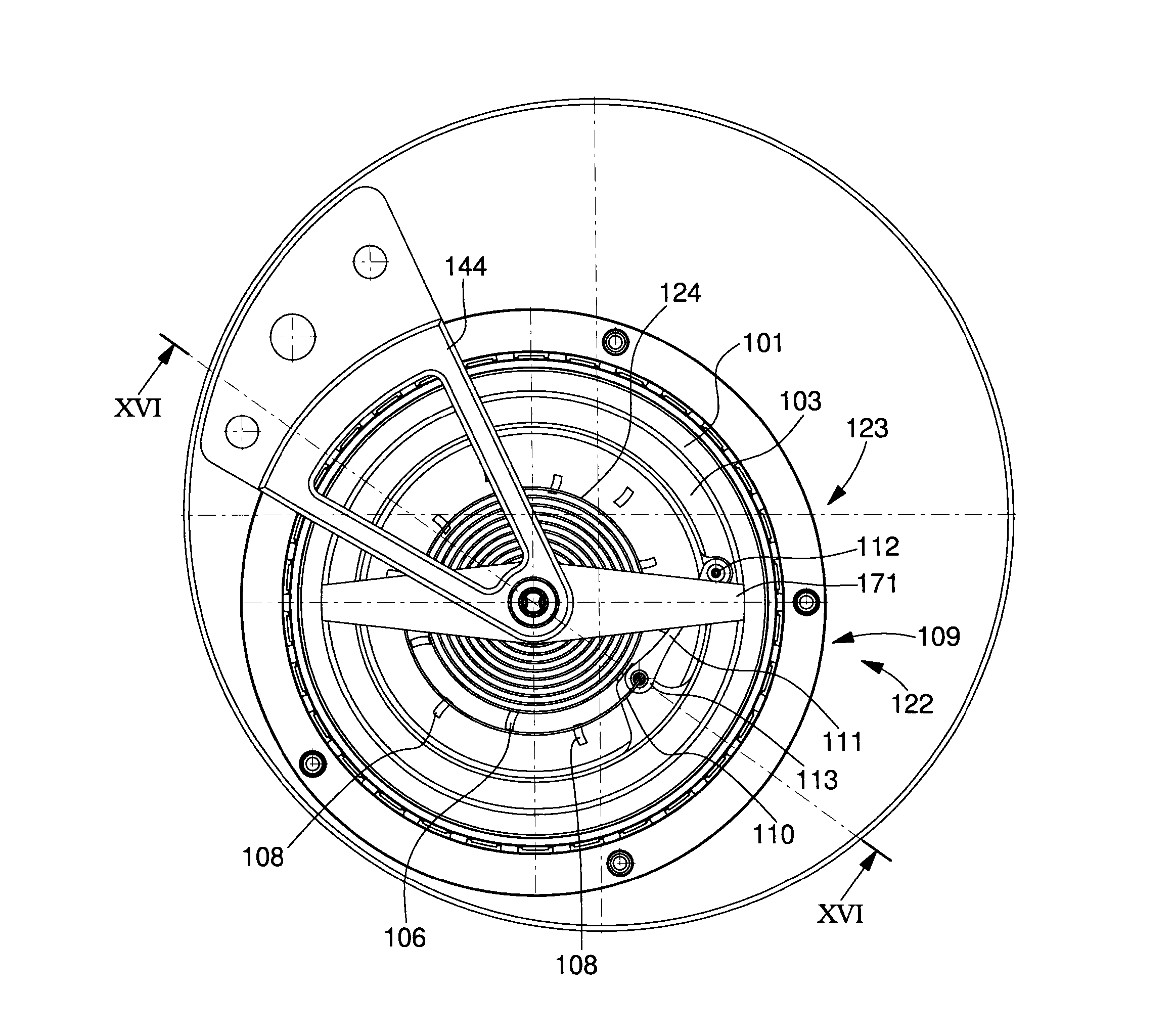
[0061]escapement system 22 according to the invention is illustrated in FIGS. 11 to 13. Escapement system 22 differs from the two preceding embodiments in that the first and second fixed wheels 5 and 7 are made in a single piece.

[0062]In order to better explain this third embodiment, FIGS. 12 and 13 are respectively cross-sections taken along XII and XIII of FIG. 11. Resonator 23 of the third embodiment is of the same type as resonator 15, of the first two embodiments. Balance 1 is thus seen again, fitted with poising screw 70 and connected to arbour 43 by means of four arms 71. Arbour 43 is pivotally mounted between bridge 44 and a bearing 72 integral with a unit 51 which incorporates, in a single piece, the outer teeth 6 and inner teeth 8 formed, in the first two embodiments, by fixed wheels 5 and 7.

[0063]Balance 1 is associated with balance spring 24 which includes more coils than balance spring 2 of the first embodiment and in which the end of the inner coil 50 is fixed to arbou...

fourth embodiment

[0065]It is also observed in FIG. 14 that the first teeth 72 have a smaller inner diameter than that of the second teeth 73. In the fourth embodiment, securing device 74 differs from device 9 of the first three embodiments. Thus, securing device 74 includes a lever 75 hinged on balance spring stud 12 carried by moving escape wheel 3. Lever 75 carries a first arm 76 at the end of which there are fixed the outer end 10 of balance spring 2 and a first impulse pin 77 arranged to cooperate with the first teeth 72 of first fixed wheel 70. Lever 75 also carries a second arm 78 at the end of which there is fixed a second impulse pin 79 arranged to cooperate with the second teeth 73 of second fixed wheel 71. Preferably, each impulse pin 77, 79 is formed of the same material as balance spring 2 or is ruby-based.

[0066]FIG. 14 shows a balance spring 2 of the type in the first embodiment in maximum expansion. The first impulse pin 77 is held locked against a first tooth 72 of the first fixed whe...


PUM


Abstract

The invention relates to a timepiece including a resonator cooperating with an escapement system. According to the invention, the escapement system includes a moving escape wheel arranged coaxially to the balance and driven by the gear train of the timepiece, a first fixed wheel having a first toothing and a second fixed wheel having a second toothing, the first and second fixed wheels being arranged coaxially to the moving escape wheel and a device for securing the outer end of the balance spring including a part hinged relative to the moving escape wheel and arranged to ensure a radial movement of the outer end between the first and second toothings to maintain the resonator and to transmit the motion thereof to the timepiece gear train.

Description

[0001]This application claims priority from European Patent application No. 13163484.2 filed Apr. 12, 2013, the entire disclosure of which is hereby incorporated herein by reference.FIELD OF THE INVENTION[0002]The invention relates to an escapement system for a sprung balance resonator and, more specifically, for a high amplitude resonator of this type.BACKGROUND OF THE INVENTION[0003]The purpose of a timepiece escapement system is to maintain and to count the oscillations of the balance wheel of a sprung balance resonator. To achieve this, the system receives the energy provided by a barrel and at the end of the chain by a seconds wheel in order to periodically allow a fragment of this drive energy to escape in order to give to the resonator energy lost through passive resistance (for example friction), the resonator including an inertia fly-wheel called a balance on the staff of which there is fixed a spiral spring called a balance spring.[0004]The mechanical energy Em of this typ...

Claims


Application Information

Patent Timeline
Patent Type & Authority Applications(United States)
IPC IPC(8): G04B15/14G04B15/00
CPCG04B15/00G04B15/14G04B15/08G04B17/285
Inventor BEUGIN, STEPHANESARCHI, DAVIDEKARAPATIS, NAKISSCIASCIA, FABIO
Owner MONTRES BREGUET
Why Eureka
Try Eureka