Undercut processing mechanism

a processing mechanism and undercut technology, applied in dough shaping, manufacturing tools, applications, etc., can solve the problems of high labor and time required for assembling, complicated construction, and difficult cost reduction, so as to reduce the number of parts, reduce the cost, and simplify the configuration of the entire molding device

Active Publication Date: 2015-01-06
TECHNOCRATS CORP
View PDF21 Cites 105 Cited by
  • Summary
  • Abstract
  • Description
  • Claims
  • Application Information

AI Technical Summary

Benefits of technology

[0008]The present invention has been made in view of the above-described problem which is posed by the conventional technique, and it is an object of the present invention to provide an undercut processing mechanism which can be configured to be compact to meet the demand for space saving, which allows easy machining of and assembling into the mold, which can achieve cost reduction, and particularly which, even in such an application as that where the undercut portion of the molded article has a geometry which is concaved and convexed in both lateral directions crossing the demolding direction, allows a larger movement stroke to be achieved in a limited installation space for easy demolding.
[0039]And yet, the undercut processing mechanism can be configured to be compact to meet the demand for space saving, allowing easy machining of and assembling into the mold, and having a simple construction, thereby the labor and time required for assembling being minimized, which allows cost reduction to be achieved.

Problems solved by technology

Therefore, as compared to the amount of movement of a piece provided with a geometry corresponding to a part of the undercut portion that is required for demolding of the undercut portion of the molded article, a large installation space is required, and as a whole, the construction becomes complicated, thereby the labor and time required for assembling being much, and the cost reduction being difficult.
In addition, the conventional technique is applicable only to an application where the undercut portion is provided outside the molded article or in a single direction in the inside thereof, and, for example, in such an application where the undercut portion which is projected from the inner portion of the bottom face of the molded article has a geometry which is concaved and convexed in both lateral directions crossing the demolding direction, it has been impossible to perform demolding of the molded article.
Therefore, not only the geometry of the undercut portion of a moldable article, but also the location thereof and the number of undercut portions have been limited to an extremely narrow range.
Particularly, the more complicated the geometry of the undercut portion becomes, the larger the movement stroke of the piece which is provided with a geometry corresponding to a part of the undercut portion that is required for demolding will be.

Method used


Image

  • Undercut processing mechanism
  • Undercut processing mechanism
  • Undercut processing mechanism

Examples


Embodiment Construction

[0052]Hereinbelow, an embodiment which represents the present invention will be explained with reference to the drawings.

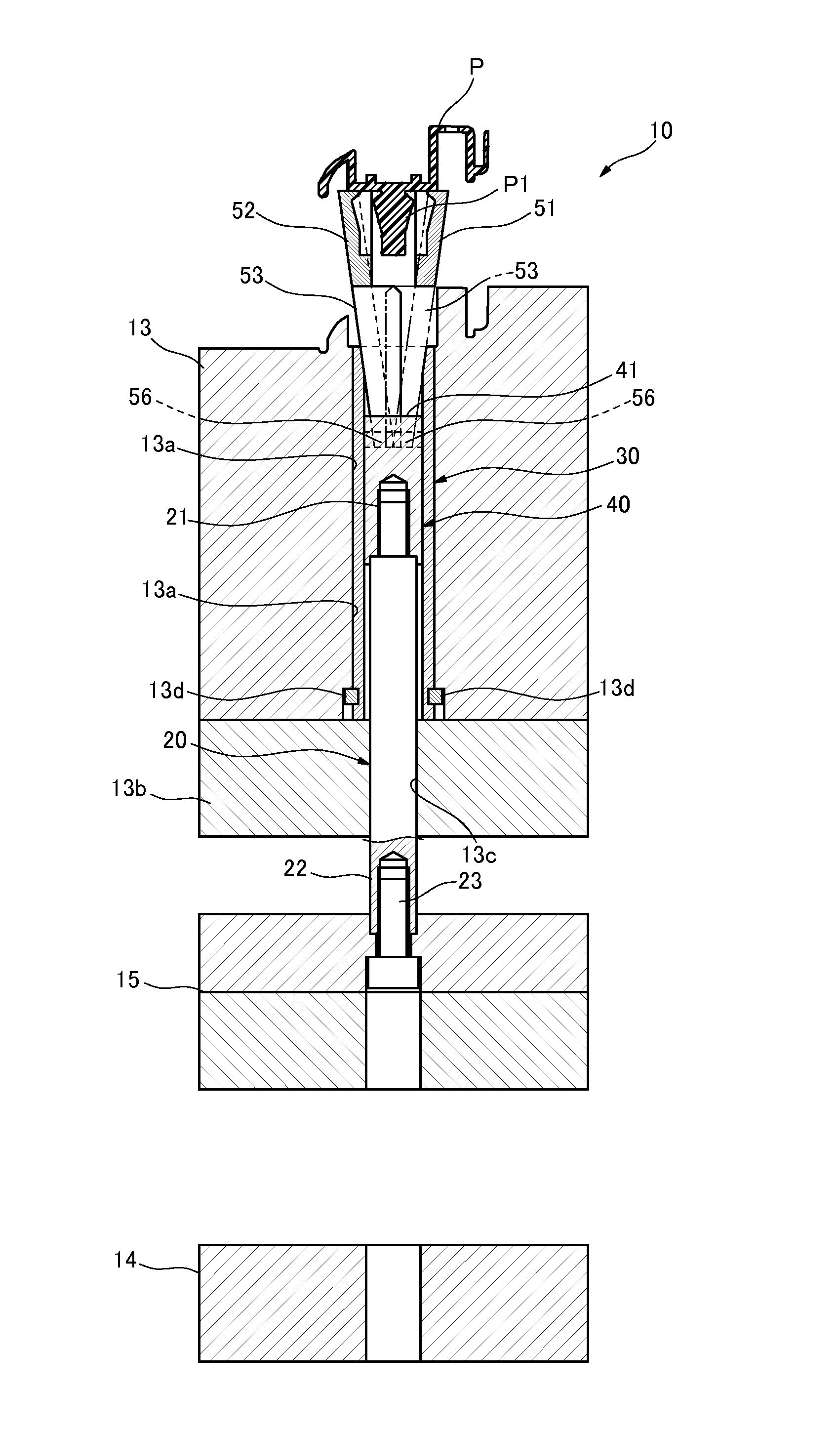
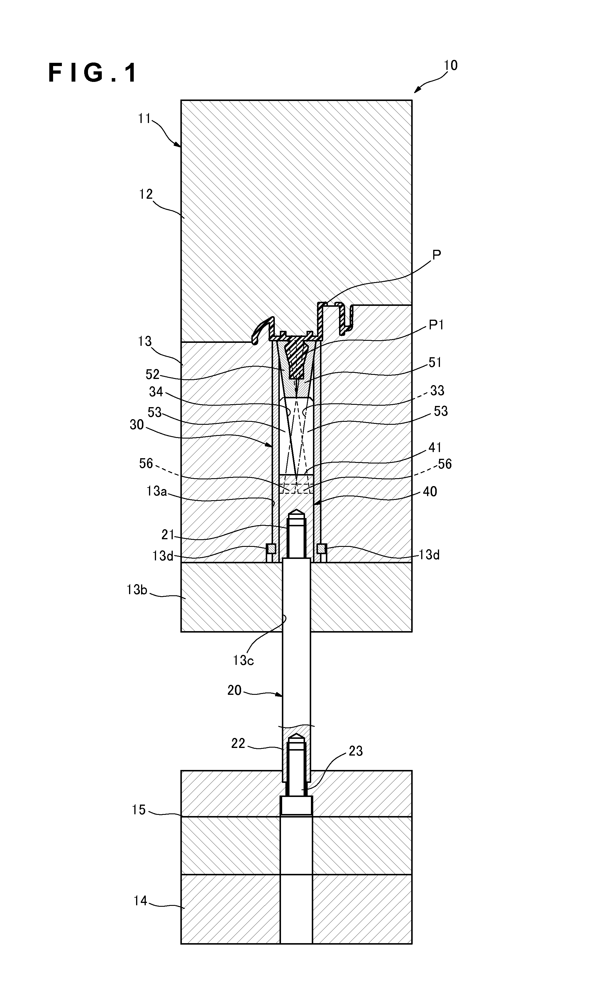
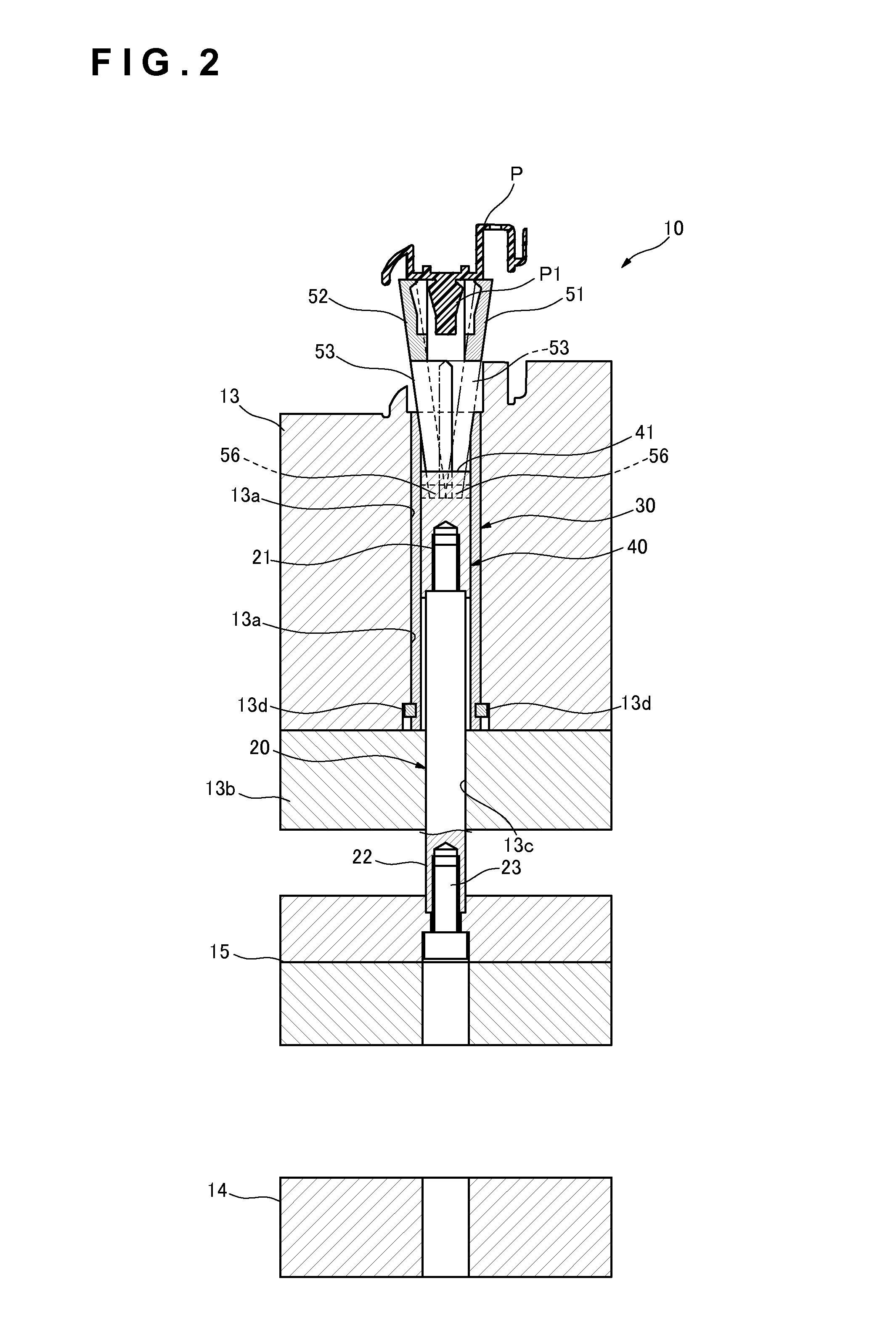
[0053]FIG. 1 to FIG. 3 are longitudinal sectional views illustrating operations of a mold 11 and an undercut processing mechanism which constitute a molding device 10 according to the present embodiment. FIG. 1 illustrates the state of an article P to be molded at the time of molding, while FIG. 2 illustrating the state of the molded article P at the time of demolding. In addition, FIG. 3 is a longitudinal sectional view of the article P to be molded when viewed from another direction, i.e., at right angles to the drawing sheet in FIG. 1 illustrating the state at the time of molding.

[0054]The molding device 10 is a device for molding the article P to be molded with the mold 11. The article P to be molded according to the present embodiment has a geometry like that of a bumper that extends in a longitudinal direction as a whole as shown in FIG. 12, and FIG. 1 to FI...


PUM

PropertyMeasurementUnit
lengthaaaaaaaaaa
movementaaaaaaaaaa
inclination angleaaaaaaaaaa

Abstract

A pair of mold cores (51, 52) for molding an undercut portion (P1) in a holder (30) installed inside a movable mold (13) are connected to and supported by a retaining piece (40) which is moved in the demolding direction, and at the time of demolding, the respective mold cores (51, 52) are guided by guide means (33, 34) from the molding position, where they are contacted with each other, to the mold release position, where they are separated from each other, being moved from one end side to the other end side of the retaining piece (40), in the mutually opposite directions so as to pass each other in the back and forth direction.

Description

TECHNICAL FIELD[0001]The present invention relates to an undercut processing mechanism which, in a mold for molding an article to be molded having an undercut portion with a stationary mold and a movable mold, brings the undercut portion into a state in which it can be demolded.BACKGROUND ART[0002]Conventionally, as a molding device of this type, a loose core ejector device disclosed in, for example, Patent Document 1, is known. The loose core ejector device includes a core of a mold for forming an inner surface of an article to be molded; a loose core support rod which is movable, penetrating through this core, and disposed slantwise with respect to the core surface; a guide rod which is locked to a movable mold plate and a pedestal plate; and a slide base which is disposed in the sliding route of the ejector plate so as to be relatively slidable in relation to this guide rod, the loose core support rod being moved in conjunction with the movement of the slide base.[0003]With such ...

Claims


Application Information

Patent Timeline
Patent Type & Authority Patents(United States)
IPC IPC(8): B29C33/44B22D17/22B22D17/24B29C33/48B29C45/44
CPCB29C33/44B29C45/4471B29C33/485B22D17/2236B22D17/24B29C45/4435Y10S425/058B22D17/22
Inventor SORIMOTO, MASANORI
Owner TECHNOCRATS CORP
Why Eureka
Try Eureka