Method and apparatus for determining formation water saturation during drilling

a technology of formation water saturation and drilling method, which is applied in the direction of instruments, surveyors, borehole/well accessories, etc., can solve the problems of unreliable water saturation values of archie-formula derived water saturation values in many carbonate formations, and forgoing instruments do not solve the challenge of invading zones with unknown water

Inactive Publication Date: 2015-01-06
SCHLUMBERGER TECH CORP
View PDF31 Cites 5 Cited by
  • Summary
  • Abstract
  • Description
  • Claims
  • Application Information

AI Technical Summary

Benefits of technology

[0020]Other aspects and advantages of the invention will be apparent from the following description and the appended claims.

Problems solved by technology

Furthermore, if the formation being evaluated has been invaded with, for example, the liquid phase of fluid (“drilling mud”) used to drill the wellbore, the connate water originally in place in the pore spaces becomes mixed with varying amounts of the drilling fluid liquid (“mud filtrate”), and the salinity of the water in the pore spaces becomes difficult or impossible to determine using only resistivity measurements.
Archie-formula derived water saturation values are therefore considered to be unreliable in many carbonate formations.
As a result, at the time such instruments are inserted into the wellbore for measurements (typically after withdrawal of drilling tools and insertion therein on an armored electrical cable) the zones of measurement of the foregoing are generally completely invaded by mud filtrate, and the water saturation measurement does not reflect the oil and / or gas contained in the uninvaded rock.
However, the foregoing is not applicable to rock formations having low salinity (i.e. less than about 50,000 parts per million [“kppm”] sodium chloride concentration) connate water, and the foregoing instrument does not solve the challenge of invaded zones having unknown water salinity.

Method used


Image

  • Method and apparatus for determining formation water saturation during drilling
  • Method and apparatus for determining formation water saturation during drilling
  • Method and apparatus for determining formation water saturation during drilling

Examples


Embodiment Construction

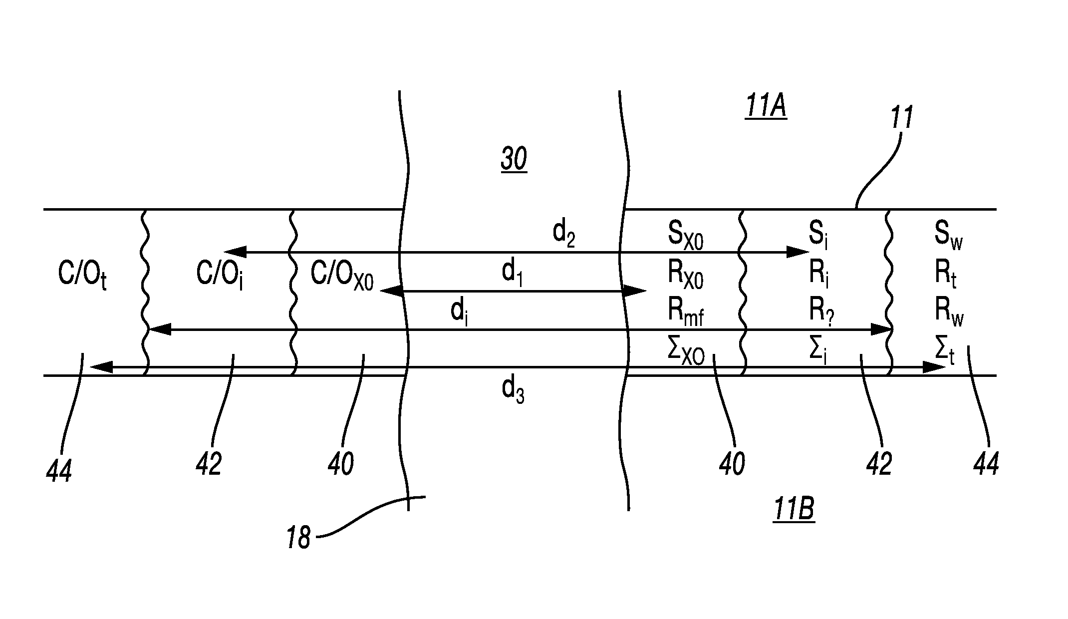
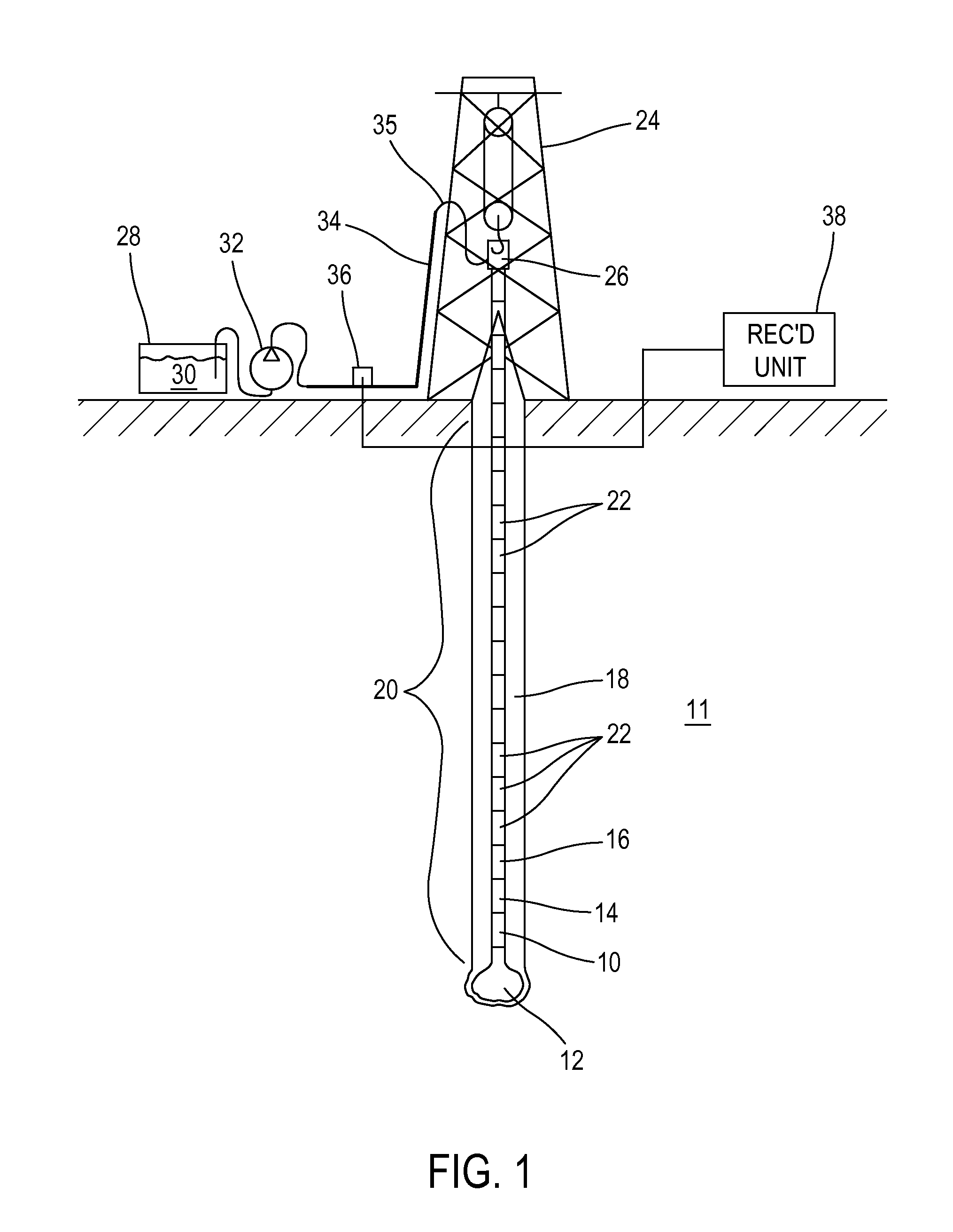
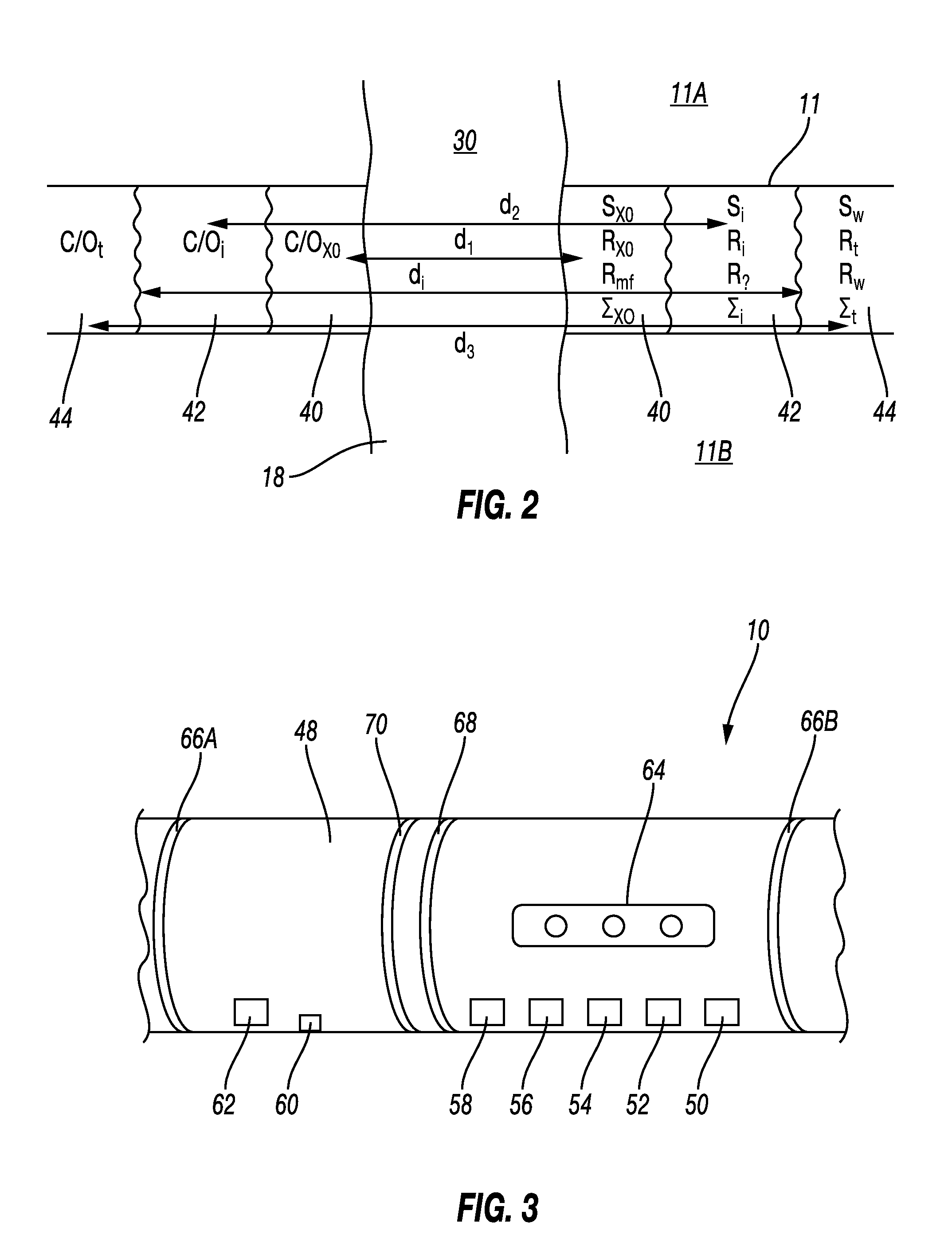
[0025]In FIG. 1, a drilling rig 24 or similar lifting device suspends a conduit called a “drill string 20” within a wellbore 18 being drilled through subsurface rock formations, shown generally at 11. The drill string 20 may be assembled by threadedly coupling together end to end a number of segments (“joints”) 22 of drill pipe. The drill string 20 may include a drill bit 12 at its lower end. When the drill bit 12 is axially urged into the formations 11 at the bottom of the wellbore 18 and when it is rotated by equipment (e.g., by a top drive 26) on the drilling rig 24, or by a motor in the drill string (not shown) such urging and rotation causes the bit 12 to axially extend (“deepen”) the wellbore 18. The lower end of the drill string 20 may include, at a selected position above and proximate to the drill bit 12, a formation evaluation sub 10 according to various aspects of the invention and which will be further explained below. Proximate its lower end of the drill string 20 may a...


PUM


Abstract

A method for determining water saturation in a subsurface formation include determining an invasion depth in the formation from a plurality of measurements made within a wellbore drilled through the formation. The measurements have different lateral depths of investigation into the formation. Carbon and oxygen in the formation are measured at substantially a same longitudinal position as at a position of the determining the invasion depth. The measured carbon and oxygen and the invasion depth are used to determine the water saturation in a substantially uninvaded part of the formation.

Description

CROSS-REFERENCE TO RELATED APPLICATIONS[0001]Not applicable.STATEMENT REGARDING FEDERALLY SPONSORED RESEARCH OR DEVELOPMENT[0002]Not applicable.BACKGROUND OF THE INVENTION[0003]1. Field of the Invention[0004]The invention relates generally to the field of petrophysical evaluation of subsurface rock formations. More specifically, the invention relates to methods and apparatus for quantitative determination of fluid saturation in pore spaces of rock formations based other than on electrical resistivity measurements of the formations.[0005]2. Background Art[0006]Porous subsurface rock formations are penetrated by wellbores for the purpose of extracting fluids from the pore spaces of such formations. In particular, oil and gas are extracted using such wellbores. It is important for economic reasons to determine what fractional volume of the pore spaces of penetrated formations are occupied by oil and / or gas prior to completion of construction of a wellbore. Methods known in the art for ...

Claims


Application Information

Patent Timeline
Patent Type & Authority Patents(United States)
IPC IPC(8): G01V3/18E21B49/08G01V5/10G01V11/00
CPCG01V5/104G01V11/00G01V3/18E21B49/08
Inventor MONTARON, BERNARD
Owner SCHLUMBERGER TECH CORP
Why Eureka
Try Eureka