
Systems and methods for high-resolution gaze tracking

a gaze tracking and high-resolution technology, applied in the field of systems and methods for high-resolution gaze tracking, can solve the problems of incomplete loss, distortion in the ability to accurately track a pupil or other reference location, and loss of glints and even overall illumination from illumination sources, so as to achieve the effect of being easy to determin

Active Publication Date: 2015-01-06
GOOGLE LLC
View PDF152 Cites 138 Cited by
  • Summary
  • Abstract
  • Description
  • Claims
  • Application Information

AI Technical Summary

Benefits of technology

[0009]The use of multiple eye tracking cameras mounted on eyewear or headwear, a component of the systems and methods of the present application, may have a number of advantages over a single camera affixed to headwear or multiple cameras located some distance away from the head. First, cameras directed at the eye from different angles may be used in a “range-finder” mode to track the locations of glints produced by illumination sources. The positions of a glint viewed from multiple angles may be used to determine camera position relative to the surface of an eye. This may be particularly useful to account for initial positions and movements of eyewear or headwear during use. Second, an individual camera directed at an eye produces two-dimensional images, whereas movements of the eyeball and other structures (e.g., eyelids, facial muscles) take place in all three (3) spatial dimensions. Image measurements from multiple cameras that view an eye from different directions may be used within anatomical model-based approaches to virtually reconstruct movements of the eye and other reference locations (e.g., glints, eye lids) in all dimensions. Third, extreme movements of the eye (i.e., up or down, left or right) may result in distortions in the ability to accurately track a pupil or other reference locations, or even the complete loss of the ability observe a pupil by a single, near-field camera due to the curvature of the eyeball and / or interference by other structures. The use of multiple cameras may permit more accurate tracking of pupils and other reference locations over a complete physiological range of eye positions.
[0028]In accordance with still another embodiment, systems and methods are provided that control the intensity of illumination sources that produce overall illumination and glint reference points on the surface of the eye. By controlling the timing of illumination relative to the timing of video image acquisition, it is possible to acquire images with and without illumination of reference glints. Subtracting images with illumination turned on, from images with illumination turned off, provides one (of several exemplary) strategies to isolate glints within images from eye tracking camera(s). Furthermore, if a single illumination source is turned on within a multiple illumination source system, then it may be easier to determine both the exact center location of the glint (i.e., compared to images that contain multiple glints) and associate a particular glint location with a specific illumination source.

Problems solved by technology

Third, extreme movements of the eye (i.e., up or down, left or right) may result in distortions in the ability to accurately track a pupil or other reference locations, or even the complete loss of the ability observe a pupil by a single, near-field camera due to the curvature of the eyeball and / or interference by other structures.
During such head movements, glints and even overall illumination can be lost from illumination sources mounted some distance away from the head.

Method used


Image

  • Systems and methods for high-resolution gaze tracking
  • Systems and methods for high-resolution gaze tracking
  • Systems and methods for high-resolution gaze tracking

Examples


Embodiment Construction

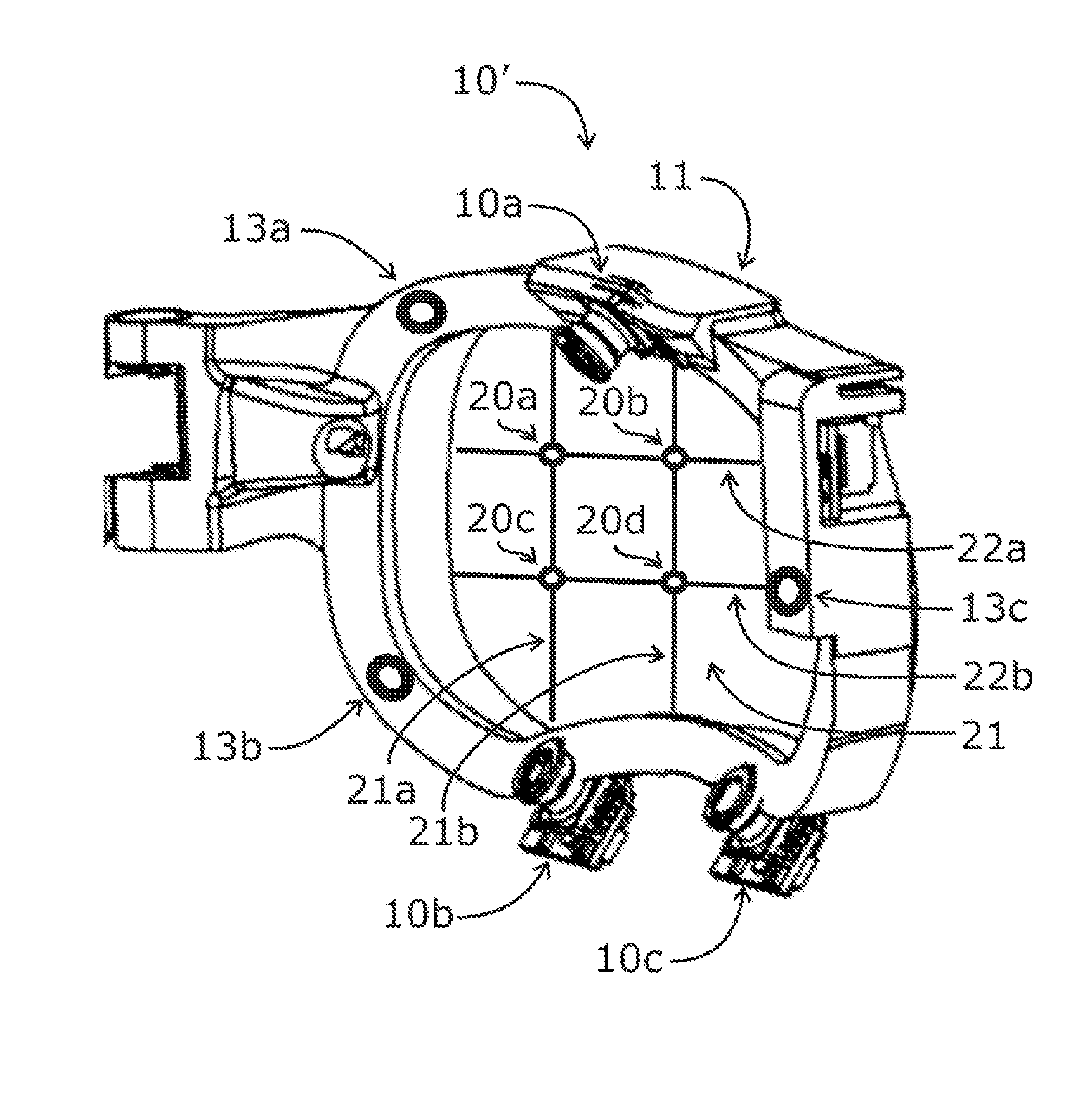
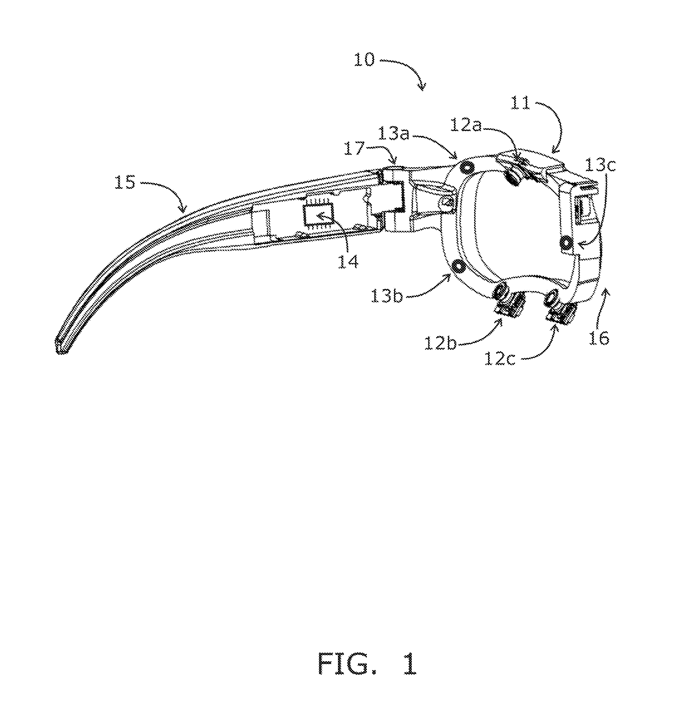
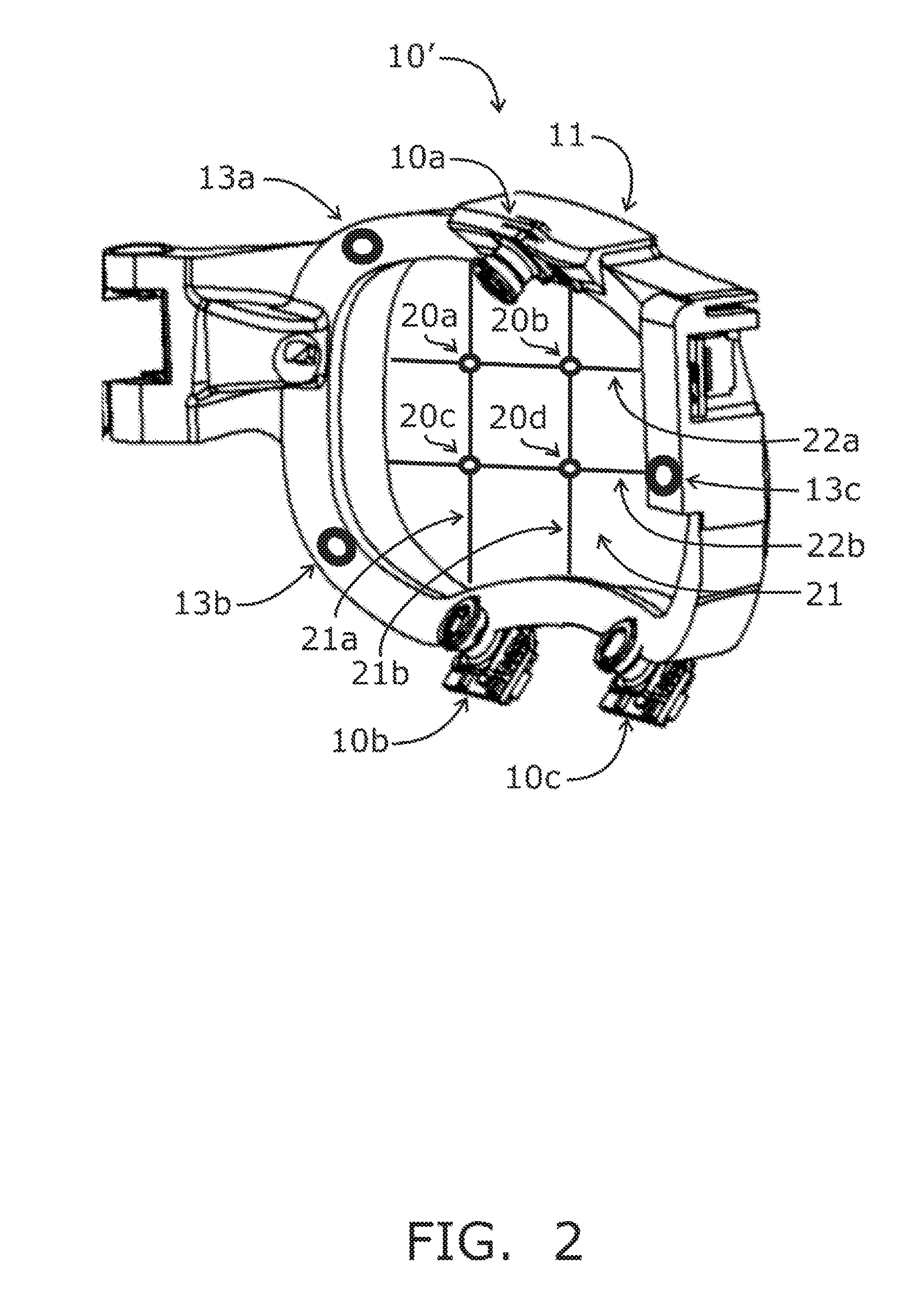
[0048]Turning to the drawings, FIG. 1 shows an exemplary embodiment of a system 10 including an eyeglass frame 11 with three eye-tracking cameras 12a, 12b, 12c directed at the left eye (not shown) of the device wearer. Also directed at the left eye of the device wearer are three illumination sources 13a, 13b, 13c, in this case, mounted on the eyeglasses frame 11. Images collected by the eye-tracking cameras 12a, 12b, 12c are sent to a processing unit 14. In this exemplary embodiment, the processing unit is mounted within the left stem 15 of the frame 11 and coupled to the cameras 12a, 12b, 12c. Optionally, to distribute weight more evenly within the eyeglass frame 11, a power source (e.g., battery, not shown) and / or other electronics may be encased in the stem of the eyeglass frame 11 opposite that containing the processing unit 14 (not shown).

[0049]The processing unit 14 may also include memory for storing image signals from the camera(s) 12a, 12b, 12c, digital filters for editing ...


PUM


Abstract

A system is mounted within eyewear or headwear to unobtrusively produce and track reference locations on the surface of one or both eyes of an observer. The system utilizes multiple illumination sources and / or multiple cameras to generate and observe glints from multiple directions. The use of multiple illumination sources and cameras can compensate for the complex, three-dimensional geometry of the head and anatomical variations of the head and eye region that occurs among individuals. The system continuously tracks the initial placement and any slippage of eyewear or headwear. In addition, the use of multiple illumination sources and cameras can maintain high-precision, dynamic eye tracking as an eye moves through its full physiological range. Furthermore, illumination sources placed in the normal line-of-sight of the device wearer increase the accuracy of gaze tracking by producing reference vectors that are close to the visual axis of the device wearer.

Description

STATEMENT REGARDING FEDERALLY SPONSORED RESEARCH AND DEVELOPMENT[0001]The U.S. Government may have a paid-up license in this invention and the right in limited circumstances to require the patent owner to license others on reasonable terms as provided for by the terms of Department of Defense (US Army) Contract No. W81XWH-05-C-0045, U.S. Department of Defense Congressional Research Initiatives No. W81XWH-06-2-0037, W81XWH-09-2-0141, and W81XWH-11-2-0156; and U.S. Department of Transportation Congressional Research Initiative Agreement Award No. DTNH 22-05-H-01424.FIELD OF THE INVENTION[0002]The present invention relates to apparatus, systems, and methods for producing accurate gaze tracking using an unobtrusive eyewear or headwear device for eye monitoring and / or control applications.BACKGROUND OF THE INVENTION[0003]The systems and methods herein utilize machine vision techniques to track the locations and / or objects being viewed by an observer. Traditionally, gaze tracking algorith...

Claims


Application Information

Patent Timeline
Patent Type & Authority Patents(United States)
IPC IPC(8): G06K9/00A61B3/113
CPCA61B3/113G06K9/00604A61B3/024G06F3/013G02B27/0093G06V40/19G06V40/193H04N23/56H04N23/90A61B3/0025G06T7/74G06T2207/30201
Inventor PUBLICOVER, NELSON G.TORCH, WILLIAM C.SPITLER, CHRISTOPHER N.
Owner GOOGLE LLC
Learn More