Method for evaluating the measurement signals of a propagation-time based measurement device

a measurement signal and propagation-time technology, applied in the direction of engine lubrication, liquid/fluent solid measurement, reradiation, etc., can solve the problems of undesired reflection, not always present, and the physical properties of the medium in the container can also change, so as to increase the accuracy and reliability of measurement

Active Publication Date: 2015-01-13
EHNDRESS KHAUZER GMBKH KO KG
View PDF18 Cites 8 Cited by
  • Summary
  • Abstract
  • Description
  • Claims
  • Application Information

AI Technical Summary

Benefits of technology

[0033]The method of the invention proves to enable an increased accuracy and reliability of the measurement, and yields, along with the unknown fill level value, further information on the fill material and the condition of the measurement device.

Problems solved by technology

A major problem for the mentioned fill level measurement devices, which work on the principle of travel time, is that the fill level measurement devices not only receive reflected signals from the fill material surface but also undesired reflections from so-called interference locations in the container.
This kind of information is not always present, however, and the physical properties of the medium in the container can also change.
Use of a polarization device is not only costly and an extra expense; often the signals cannot even be polarized, for example in the case of single-wire- or coaxial-waveguides of a TDR fill level measurement device.

Method used


Image

  • Method for evaluating the measurement signals of a propagation-time based measurement device
  • Method for evaluating the measurement signals of a propagation-time based measurement device
  • Method for evaluating the measurement signals of a propagation-time based measurement device

Examples


Embodiment Construction

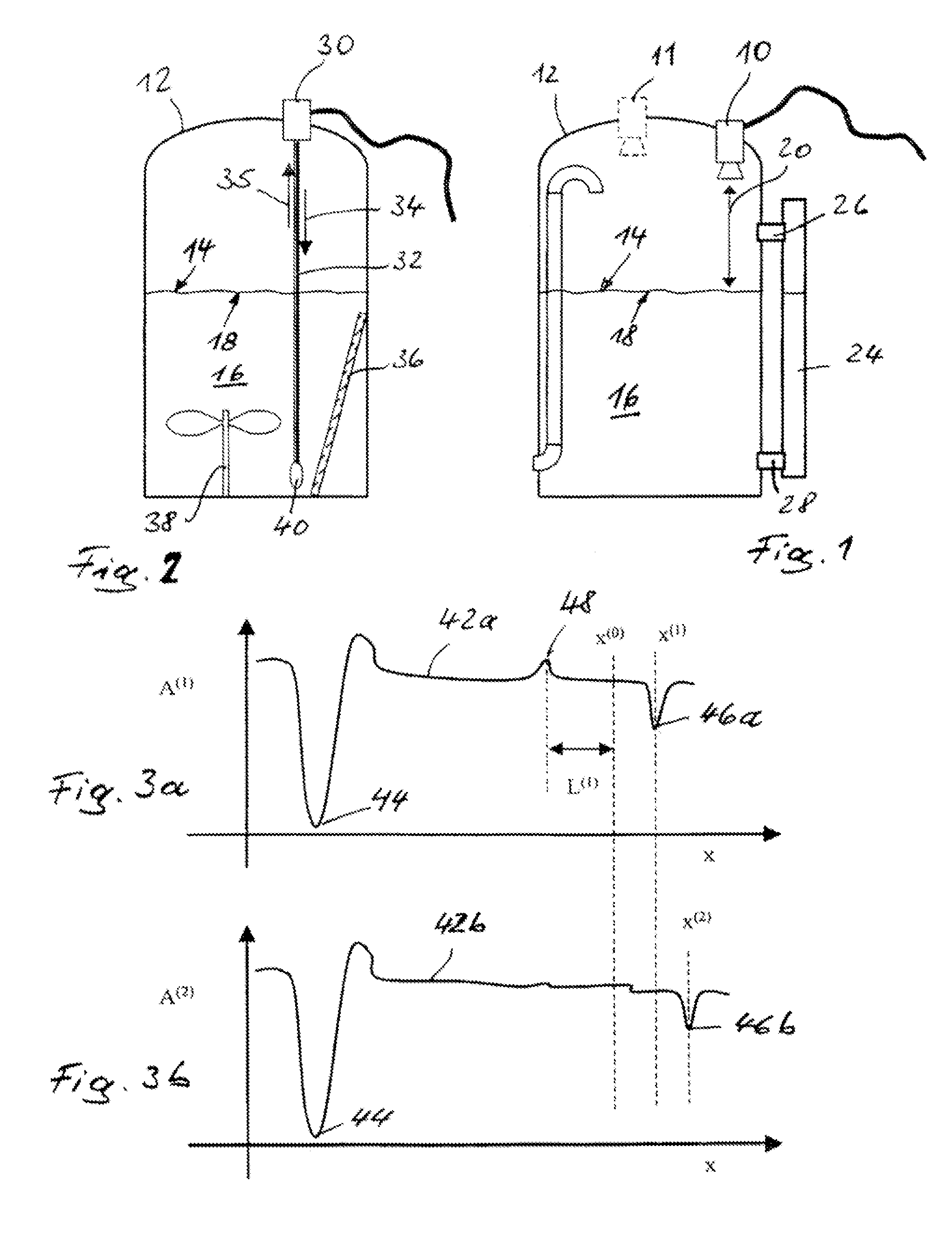
[0046]FIG. 1 shows schematically, and by way of example, a typical arrangement of a fill level measurement device 10 based on the use of radar, mounted on a container 12 and protruding into such. The radar fill level measurement device 10, which serves for determining the fill level 14 of a medium 16 present in the container 12, is electrically serviced over a cable, which is illustrated only schematically, and connected, for example, with a monitor (not shown). The radar fill level measurement device 10 transmits for this purpose, from the schematically indicated horn antenna, radar signals, preferably pulsed measurement signals, in the direction onto the medium 16. These signals are reflected on a surface 18 of the medium 16. This is indicated by the double arrow 20 in FIG. 1. The reflected measurement signals are received by the horn antenna and compared in the radar fill level measurement device 10 with the transmitted measurement signals. The time from the transmitting of a mea...


PUM


Abstract

A method which allows especially the extrapolation of the measured value at the upper and lower end of a measuring range where normally no direct measurement range where normally no direct measurement is possible by superposition of interfering signals, for example by reflection on a radar antenna. In the presence of strong interference signals, for example by reflection of a radar antenna. In the presence of strong interference signals, which are for example caused by the natural resonance of the container or neck in which the measuring device is mounted, the direct level indicator signal can be regularly used if it has a high amplitude caused by a superposition with the interfering signal lies between two interfering signals and does not extend beyond these, the level indicator value can be interpolated by the shift of the signals from the point of reflection. The inventive method automatically adapts itself to a prevailing measuring situation while according to known methods for the user has to decide between a measurement via a shift of EOL signal or a measurement via the direct level indicator echo.

Description

TECHNICAL FIELD[0001]The invention relates to a method for determining the fill level of a medium in a container by means of a fill level measurement device which works on the basis of travel, or propagation, time.BACKGROUND OF THE INVENTION[0002]Fill level measurement devices of this type are known per se; they are usually mounted above the medium, also called “fill material”, in, or at, the container. For determining the fill level of the medium, high frequency signals, ultrasonic signals or optical signals generated in the fill level measurement device are sent from the measurement device in the direction onto the medium, where they are reflected at a surface of the medium. These reflected signals, also called the useful signals, are registered by the fill level measurement device. Their travel time is a measure for the distance of the measurement device from the reflecting surface of the medium. Combined with knowledge of the container geometry, the fill level of the medium in t...

Claims


Application Information

Patent Timeline
Patent Type & Authority Patents(United States)
IPC IPC(8): G01F23/00G01F23/284
CPCG01F23/0076G01F23/284G01F25/0061G01S13/00G01F23/28G01F23/2962G01S7/292G01S13/88G01F23/804G01F25/20
Inventor MULLER, ROLANDSCHROTH, HERBERTCRAMER, STEFAN
Owner EHNDRESS KHAUZER GMBKH KO KG
Why Eureka
Try Eureka