Head packaging for cylinder deactivation

a technology for packaging and cylinders, applied in the direction of valve arrangements, combustion engines, machines/engines, etc., can solve the problems of reducing affecting the efficiency of cylinder deactivation mechanisms, and requiring more space for deactivating valves or enabling a third lift profile. , to achieve the effect of increasing fuel efficiency and fuel efficiency

Active Publication Date: 2015-01-13
FORD GLOBAL TECH LLC
View PDF17 Cites 18 Cited by
  • Summary
  • Abstract
  • Description
  • Claims
  • Application Information

AI Technical Summary

Benefits of technology

[0001]Variable displacement engine (VDE) designs are well known in the art for providing increased fuel efficiency by deactivating cylinders during operation modes requiring decreased engine output. Such designs may also incorporate cam profile switching (CPS) to enable high or low lift valve train modes which correspond to increased fuel efficiency during high and low engine speeds, respectively.
[0005]In this way, an engine cylinder head design in which a third, zero-lift profile may be included in some cylinders having both first and second lift profiles. For example, a cylinder head may be enabled with a camshaft having high and low lift cam profiles on all cylinders, and selective deactivation of outer cylinders only by inclusion of a third, zero-life profile on these cylinders. Such an approach utilizes additional space located on the outer camshaft as per some pre-existing engine cylinder head designs and asymmetrical cam tower placement to allow sufficient space for the different cam profiles over both outer and inner cylinders without intruding on inner cylinder spacing. Such an approach has the potential advantage of enabling VDE and CPS concurrently in a more compact engine design such as an inline, four-cylinder engine. Further, such an approach may enable flexibility of using the same engine architecture on multiple vehicle platforms.

Problems solved by technology

However, the inventors herein have recognized that such an approach does not incorporate three distinct lift profiles for one cylinder.
Generally speaking, mechanisms for deactivating valves or enabling a third lift profile require more space along the length of an overhead camshaft.
The placement of cam towers and cylinder bore spacing requirements further inhibit the inclusion of multiple valve lift profiles and / or cylinder deactivation mechanisms.

Method used


Image

  • Head packaging for cylinder deactivation
  • Head packaging for cylinder deactivation
  • Head packaging for cylinder deactivation

Examples


Embodiment Construction

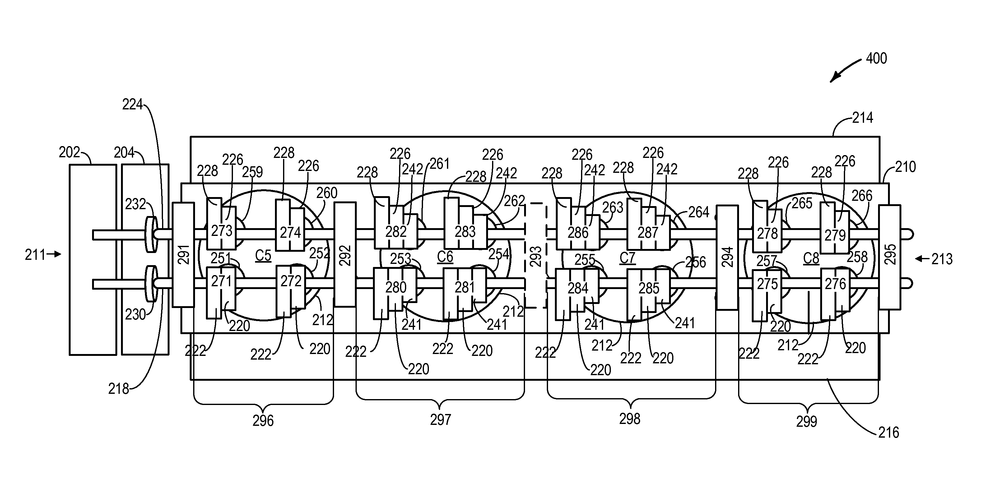
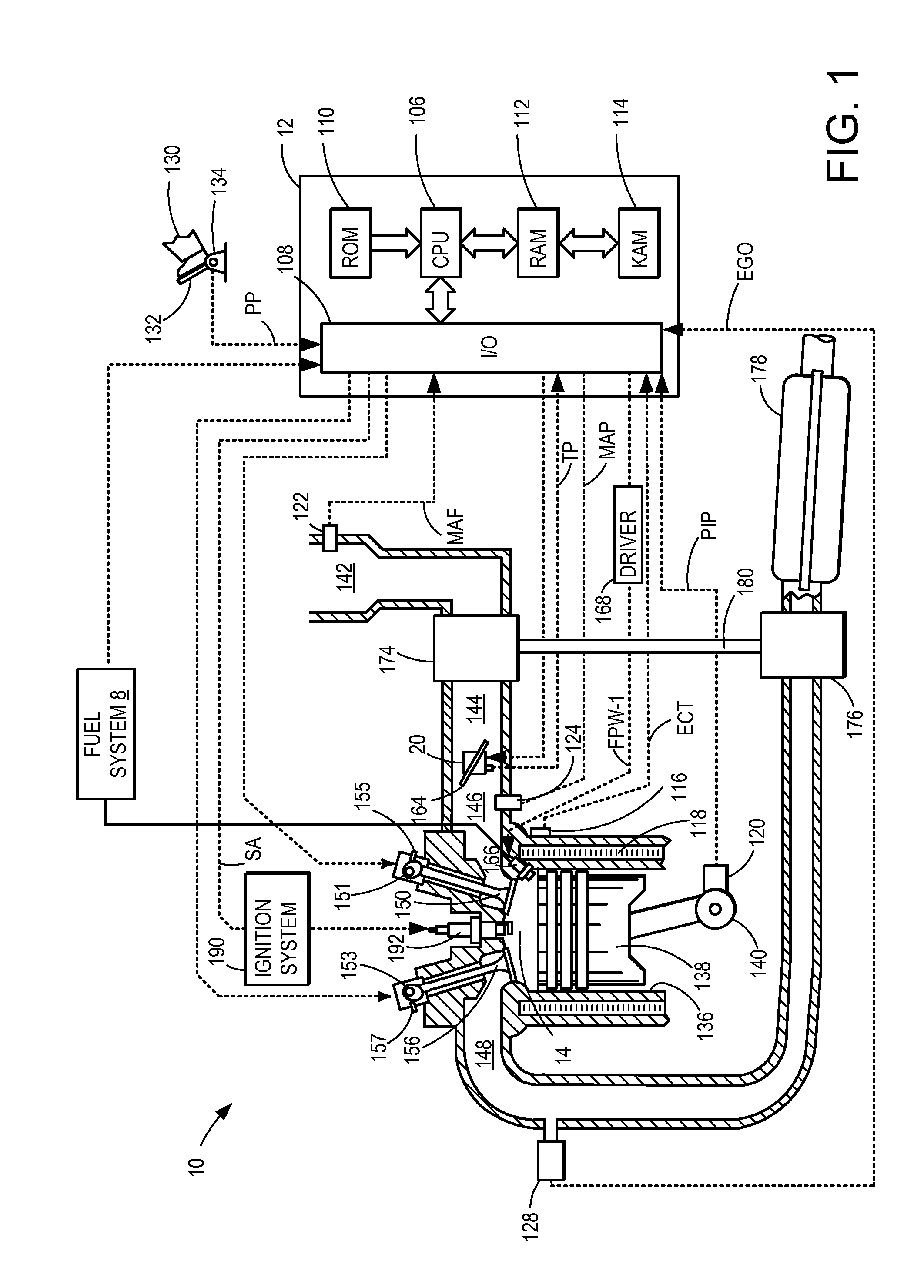
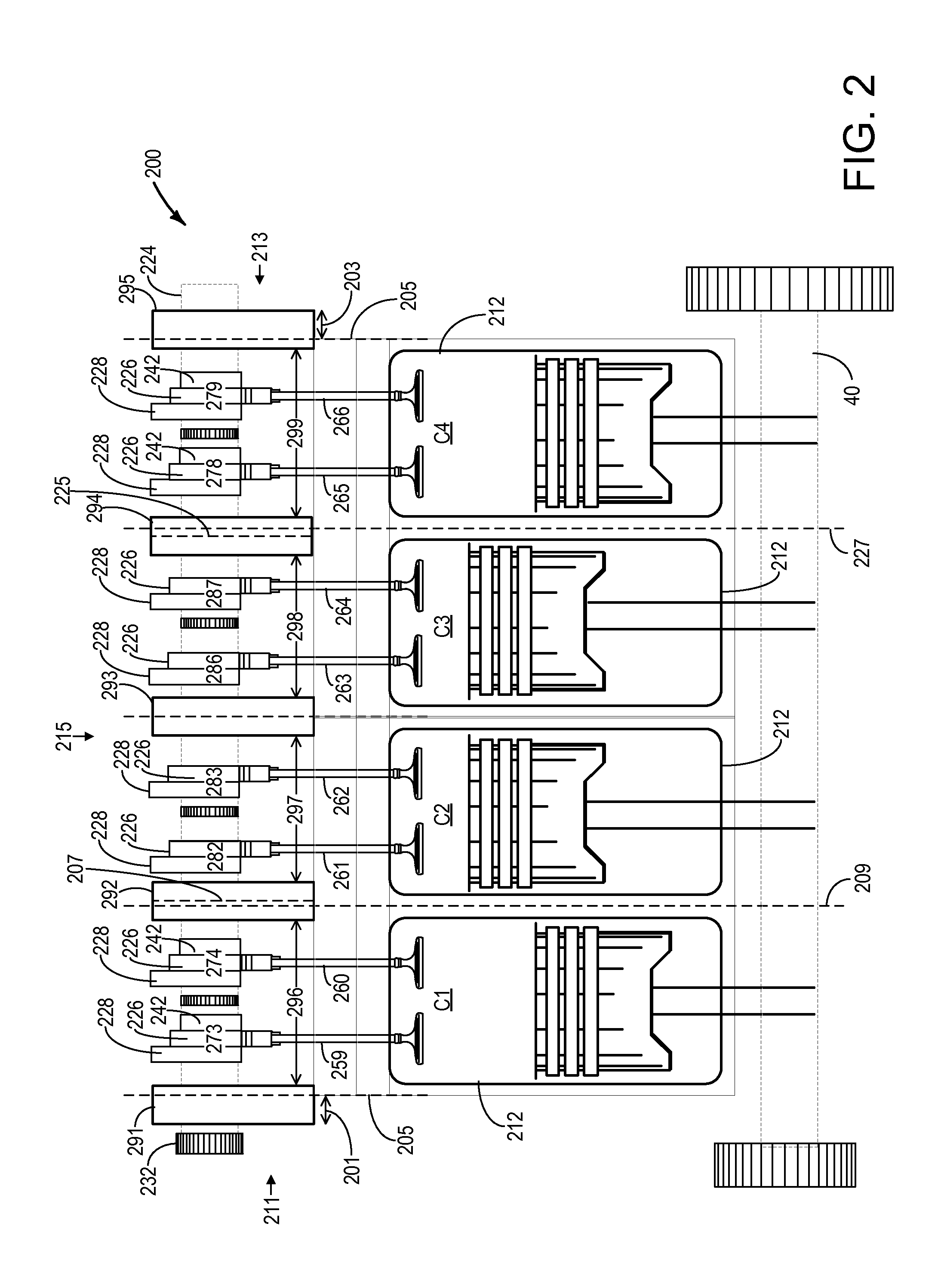
[0012]The following description relates to an internal combustion engine, such as the engine shown in FIG. 1, having a cylinder bank and cylinder head enabled with a cam-profile-switching (CPS) system and variable-displacement engine (VDE) modes. As shown in FIGS. 2 and 3, an engine cylinder head may be designed to permit deactivation of valves on outer cylinders using wider mechanisms on the outer cylinders compared to the mechanisms on inner cylinders which do not deactivate. In other examples, as shown in FIG. 4, an engine cylinder head may be designed to permit deactivation of valves on inner cylinders using wider mechanisms on the inner cylinders compared to the mechanisms on outer cylinders which do not deactivate. As described in FIG. 5, such a cylinder head configuration may be used to adjust valve lift profiles on both inner and outer cylinders and to deactivate outer cylinders based on engine operating conditions.

[0013]Turning now to the figures, FIG. 1 depicts an example ...


PUM


Abstract

Systems and methods for an overhead cam shaft coupled to an inline engine with inner cylinders and outer cylinders are disclosed. In one example approach, an engine bank comprises inner cylinders each having only first and second lift profiles, both being non-zero lift profiles, and outer cylinders each having first, second, and third lift profiles, two being non-zero lift profiles and one being zero lift.

Description

BACKGROUND AND SUMMARY[0001]Variable displacement engine (VDE) designs are well known in the art for providing increased fuel efficiency by deactivating cylinders during operation modes requiring decreased engine output. Such designs may also incorporate cam profile switching (CPS) to enable high or low lift valve train modes which correspond to increased fuel efficiency during high and low engine speeds, respectively.[0002]In CPS systems, a VDE design may be supported through a no-lift cam profile that deactivates cylinders based on engine output needs. As an example, U.S. Pat. No. 6,832,583 describes an engine valve train having multiple valve lift modes including cylinder deactivation. The described example utilizes high and low lift cams on the valve train which can be further modified so that low lift corresponds to a zero-lift deactivation setting.[0003]However, the inventors herein have recognized that such an approach does not incorporate three distinct lift profiles for one...

Claims


Application Information

Patent Timeline
Patent Type & Authority Patents(United States)
IPC IPC(8): F01L1/34F01L1/053F01L1/20F01L1/344F01L13/00F02B75/18F02D13/06
CPCF01L13/0036F02D13/06F01L1/20F01L1/344F01L13/0005F01L2001/0537F01L2013/0052F02B2075/1816Y02T10/18F02B75/20Y02T10/12F01L1/053
Inventor MCCONVILLE, GREGORY PATRICKKU, KIM HWE
Owner FORD GLOBAL TECH LLC
Why Eureka
Try Eureka